4.2.4.19
Upper Paper Guide L/R / PE Sensor
Parts/Components need to be removed in advance:
Main Frame/Printhead/CR Scale/Carriage Unit/Ink System/Transmission Holder
Assy/Front Frame/Rear Frame/Lower Paper Guide Waste Ink Pad Assy
Removal procedure
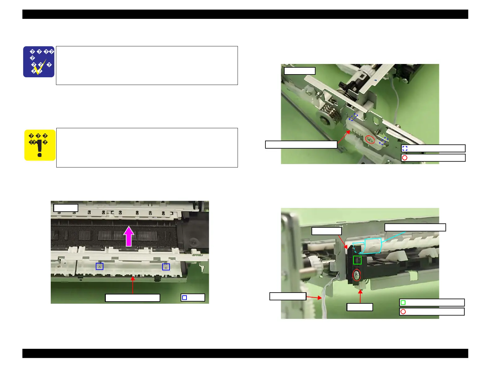
Upper Paper Guide L
1.
Release the hooks (x2) of the Main Frame, and remove the Upper Paper
Guide L in the direction of the arrow.
Figure 4-147. Removing the Left Paper Guide
Upper Paper Guide R/PE Sensor
1.
Remove the screw (x1) that secures the Sub Transmission Cam Holder and
remove the Sub Transmission Cam Holder.
Figure 4-148. Removing the Upper Paper Guide R/PE Sensor
2.
Disconnect the PE Sensor cable from the connector. (See Fig. 4-149.)
3.
Remove the screw (x1) that secures the PE Sensor, and remove the PE Sensor
avoiding the damage to the Upper Paper Guide sheet.
Figure 4-149. Removing the PE Sensor
The Main Frame becomes unstable once it is removed from the
Base Frame. Be careful not to deform the frame during
performing the following procedures.
◼
Refer to 4.2.4.11 Main Frame (p144) for the Parts/Components
need to be removed before removing the Main Frame.
Be careful not to touch or damage the roller of the Upper Paper
Guide L/R, or it can adversely affect print quality.
 Loading...


