Epson Artisan 800/Epson Stylus Photo PX800FW/TX800FW/Epson Artisan 700/Epson Stylus Photo PX700W/TX700W
Disassembly Procedures
https://www.manualsbooks.com
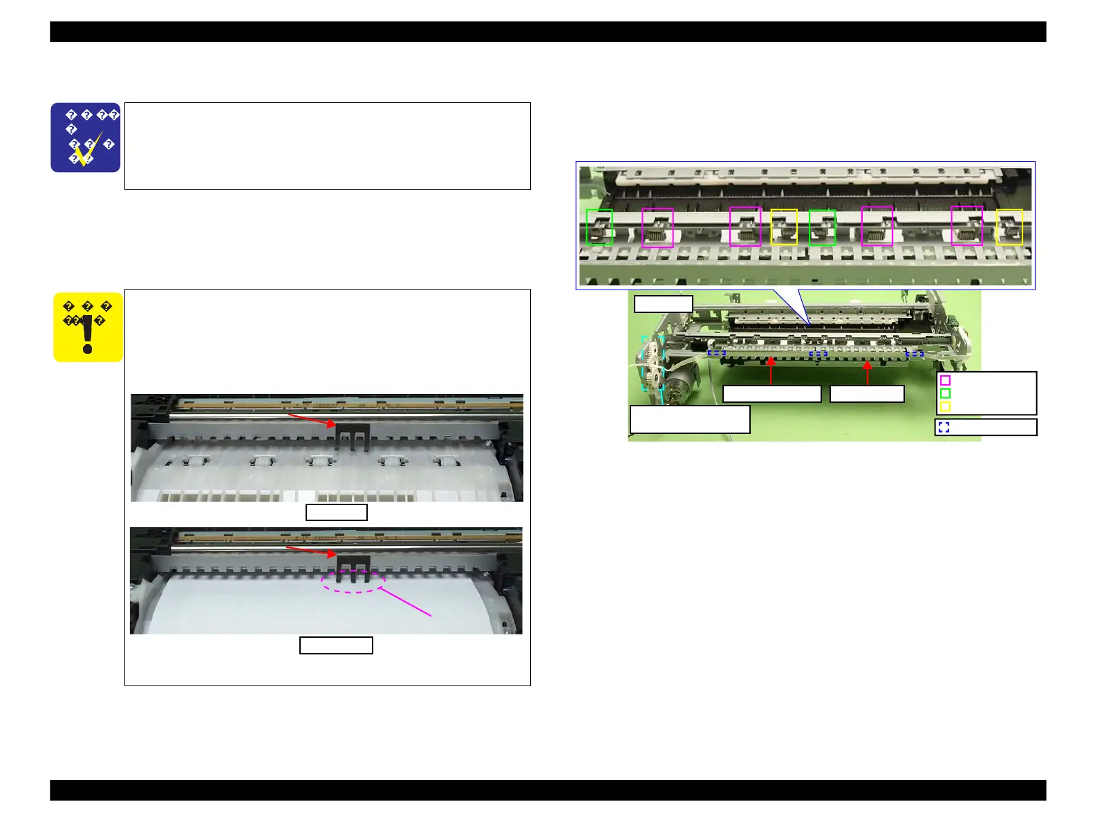
Deformed antistatic cloth attached on the Rear Frame will cause
ink mist adhering to the print surface; therefore, make sure not to
touch the antistatic cloth.
If it is deformed, make sure to repair it so as to let it touch the paper
as shown in below figure.
Figure 4-143. Position of the antistatic cloth
Antistatic cloth must touch the paper.
4.2.4.18
Rear Frame
Parts/Components need to be removed in advance:
Main Frame/Printhead/CR Scale/Carriage Unit/Front Frame/Ink System/
Transmission Holder Assy
Removal procedure
1.Peel off the PF Encoder FFC from the Rear Frame. (See Fig. 4-144.)
2.Remove the Torsion Spring A (x4), B (x2) and C (x2). (See Fig. 4-144.)
3.Remove the Spur Gears (x2) and Combination Gear (x1). (See 4.2.4.15 CR
Motor Step2 (p152).)
Figure 4-144. Removing the Rear Frame (1)
Torsion Spring A
Torsion Spring B
Torsion Spring C
Spur Gear (x2)
Combination Gear (x1)
The Main Frame becomes unstable once it is removed from the
Base Frame. Be careful not to deform the frame during
performing the following procedures.
◼
Refer to 4.2.4.11 Main Frame (p144) for the Parts/Components
need to be removed before removing the Main Frame.
 Loading...


