Epson Artisan 800/Epson Stylus Photo PX800FW/TX800FW/Epson Artisan 700/Epson Stylus Photo PX700W/TX700W
Disassembly Procedures
https://www.manualsbooks.com
4.2.4.15
CR Motor
Parts/Components need to be removed in advance:
Main Frame
Removal procedure
1.
Loosen the CR Timing Belt, and detach the CR Timing Belt from the Pinion
Gear of the CR Motor. (See 4.2.4.16 Carriage Unit Step2 - Step4 (p155).)
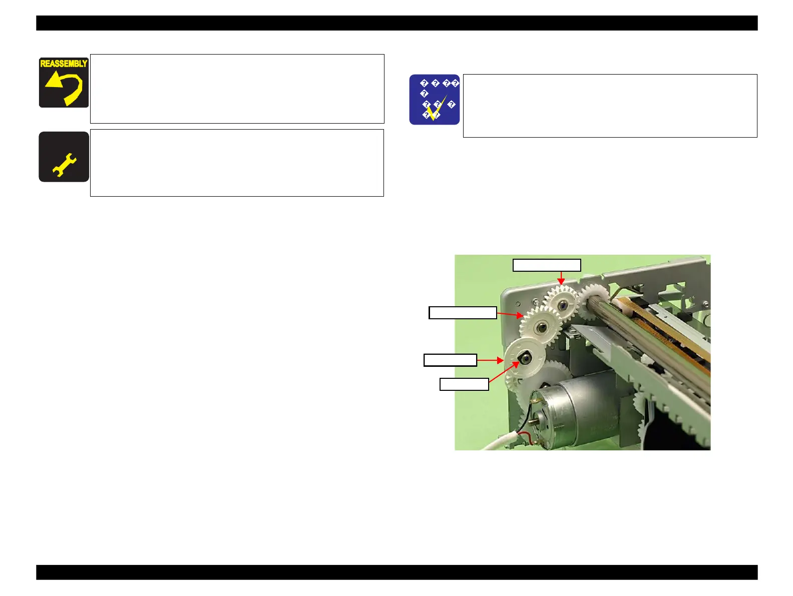
2.
Remove the securing ring that secures the Spur Gear A, and remove the Spur
Gears (A, B) and Combination Gear (x1).
Figure 4-124. Removing the CR Motor (1)
Align the positioning holes (x2) of the Holder with the dowels
(x2) of the Main Frame. (See Fig. 4-120.)
Insert the Compression Spring to the dowel of the Tensioner
and attach it to the protrusion of the Tension Holder
reinforcing plate. (See Fig. 4-119.)
After removing/replacing the PF Motor, make the specified
adjustments. (See Chapter 5 "ADJUSTMENT".)
After replacing the PF Motor, be sure to perform the required
lubrication. (See Chapter 6 "MAINTENANCE".)
The Main Frame becomes unstable once it is removed from the
Base Frame. Be careful not to deform the frame during
performing the following procedures.
◼
Refer to 4.2.4.11 Main Frame (p144) for the Parts/Components
need to be removed before removing the Main Frame.
 Loading...


