Epson Artisan 800/Epson Stylus Photo PX800FW/TX800FW/Epson Artisan 700/Epson Stylus Photo PX700W/TX700W
Disassembly Procedures
https://www.manualsbooks.com
5.
Remove the screws (x2) that secure the Tension Holder reinforcing plate and
remove the Holder.
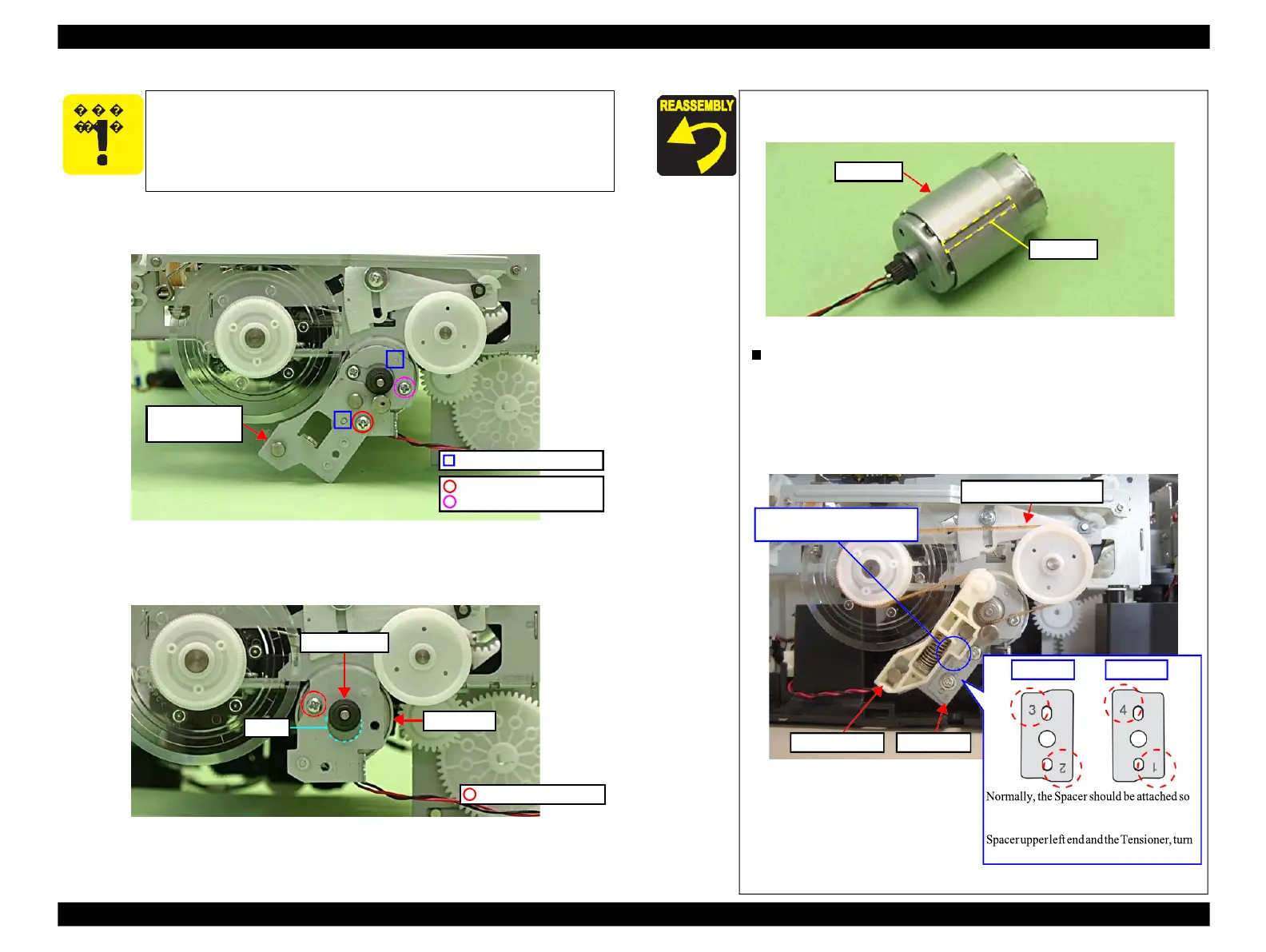
Figure 4-120. Removing the PF Motor (3)
6.
Remove the screw (x1) that secures the PF Motor, and remove the PF Motor
while drawing out the Pinion Gear from the hole of the Main Frame.
Figure 4-121. Removing the PF Motor (4)
Be careful not to damage the Pinion Gear of the PF Motor.
When installing the PF Motor, keep the groove of the PF Motor
upward.
Figure 4-122. Installing the PF Motor
When installing the Spacer, align the positioning holes (x2) of the
Spacer with the dowels (x2) of the Holder.
Make sure there is no gap between upper left end of the Spacer
and the Tensioner. If there is a gap, turn the Spacer around or
over so that another letter (2, 4, or 1 ) comes to the upper left and
install it. (See Fig. 4-118 and Fig. 4-123.)
PF Timing Belt
No gap between the Spacer and
that the letter "3" on it comes to upper left.
However, if you see a gap between the
the Spacer around or over and install it.
Figure 4-123. Installing the Spacer
C.B.S. 3x6 (8±1Kgfcm)
C.P. 3x5 (4±0.5Kgfcm)
Tension Holder
reinforcing plate
 Loading...


