Epson Artisan 800/Epson Stylus Photo PX800FW/TX800FW/Epson Artisan 700/Epson Stylus Photo PX700W/TX700W
Disassembly Procedures
https://www.manualsbooks.com
4.2.6.8
ADF Frame Unit
Parts/Components need to be removed in advance:
Scanner Unit/ADF Unit/ADF Cover Assy/ADF Right Cover/ADF Rear Cover/
ADF Cover Stacker/ADF Document Support Cover/ADF Front Cover/ADF
Document Support Assy
Removal procedure
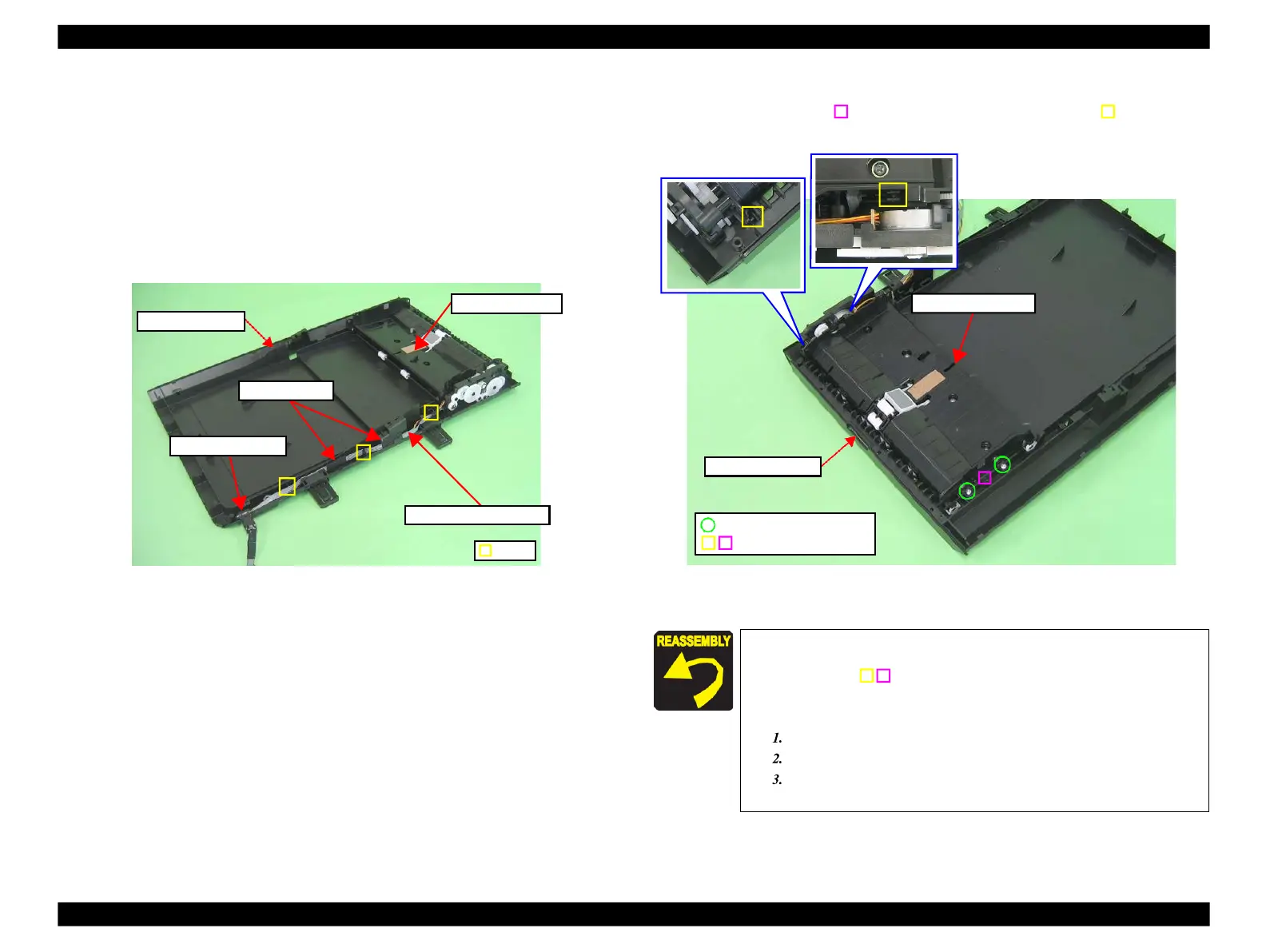
1.
Peel off the acetate tape (x2), and release the cable of the ADF Unit from the
ADF Base Assy.
Figure 4-191. Removing the ADF Frame Unit (1)
2.
Remove the screws (x2) that secure the ADF Frame Unit.
3.
Release the dowel (x1) of the ADF Base and the dowels (x2) of the
ADF Frame Unit, then remove the ADF Frame Unit from the ADF Base Assy.
Figure 4-192. Removing the ADF Frame Unit (2)
C.B.P. 3x8 (6±1kgfcm)
Positioning hole & dowel
When installing the ADF Frame Unit, align the positioning
holes (x3) of the ADF Frame Unit and ADF Base Assy with the
dowels (x3) as shown in Fig. 4-192.
Route the ADF Motor cable, ADF Sensor cable, and the
Grounding Wire as follows, referring to Fig. 4-191.
Route them through the grooves (x3) of the ADF Base Assy.
Attach the ADF Cable Cover to the ADF Base Assy.
Secure the cables to the ADF Base Assy with acetate tape
 Loading...


