Epson Artisan 800/Epson Stylus Photo PX800FW/TX800FW/Epson Artisan 700/Epson Stylus Photo PX700W/TX700W
Disassembly Procedures
https://www.manualsbooks.com
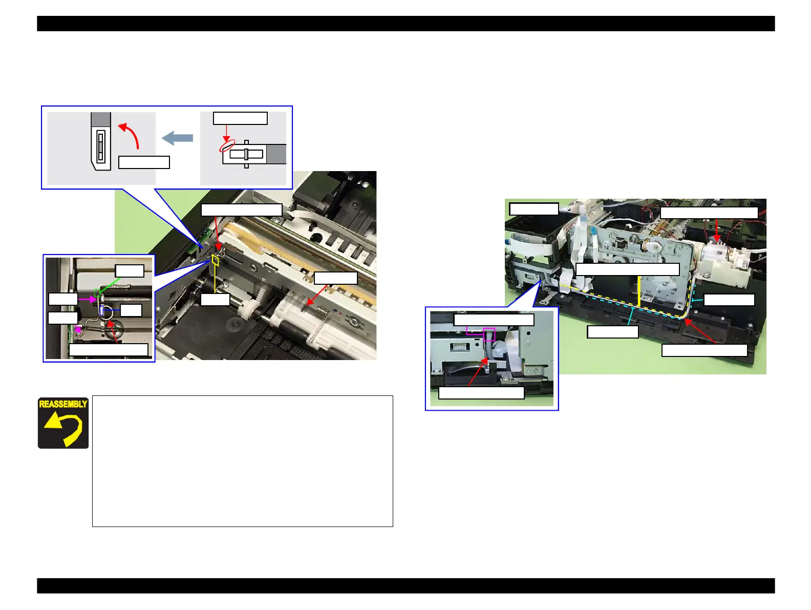
4.
Detach the Torsion Spring 16.43 from the hook of the Main Frame.
5.
Rotate the CR Scale 90 degrees as shown below, and remove it from the Main
Frame.
Figure 4-70. Removing the CR Scale(2)
4.2.4.3
Decompression Pump Unit
Parts/Components need to be removed in advance:
ADF Unit (Artisan 800/PX800FW/TX800FW only)/Scanner Unit/Upper Left
Housing/Paper Guide Top Assy/Upper Housing/Hinge/Rear Right FAX Housing/
Right Housing/Main Board
Removal procedure
1.
Remove the decompression tube from the socket of the Cartridge Box Unit.
(See Fig. 4-71.)
2.
Release the decompression tube from the groove on the Base Frame.
Figure 4-71. Removing the Decompression Pump Unit
Attach the CR Scale to the hook on the left of the printer with
the chipped part upward. (See Fig. 4-70.)
Make sure to put the CR Scale through the slit of the CR
Encoder Sensor. (See Fig. 4-69.)
When installing the Torsion Spring 16.43, follow the procedure
below. (See Fig. 4-70.)
1.
Attach the leg A to the hole of the CR Scale.
2.
Attach the Torsion Spring 16.43 to the rib on the Main
Frame.
3.
Attach the leg B to the cutout of the Main Frame.
 Loading...


