Epson Artisan 800/Epson Stylus Photo PX800FW/TX800FW/Epson Artisan 700/Epson Stylus Photo PX700W/TX700W
Disassembly/reassembly procedures specific to Artisan 700/PX700W/TX700W
https://www.manualsbooks.com
4.3.2.2
Main Board/Grounding Plate M/B (Artisan 700/PX700W/
TX700W)
Parts/Components need to be removed in advance:
Scanner Unit/Upper Left Housing/Paper Guide Top Assy/Upper Housing/Hinge/
Rear Right Housing/Right Housing
Removal procedure
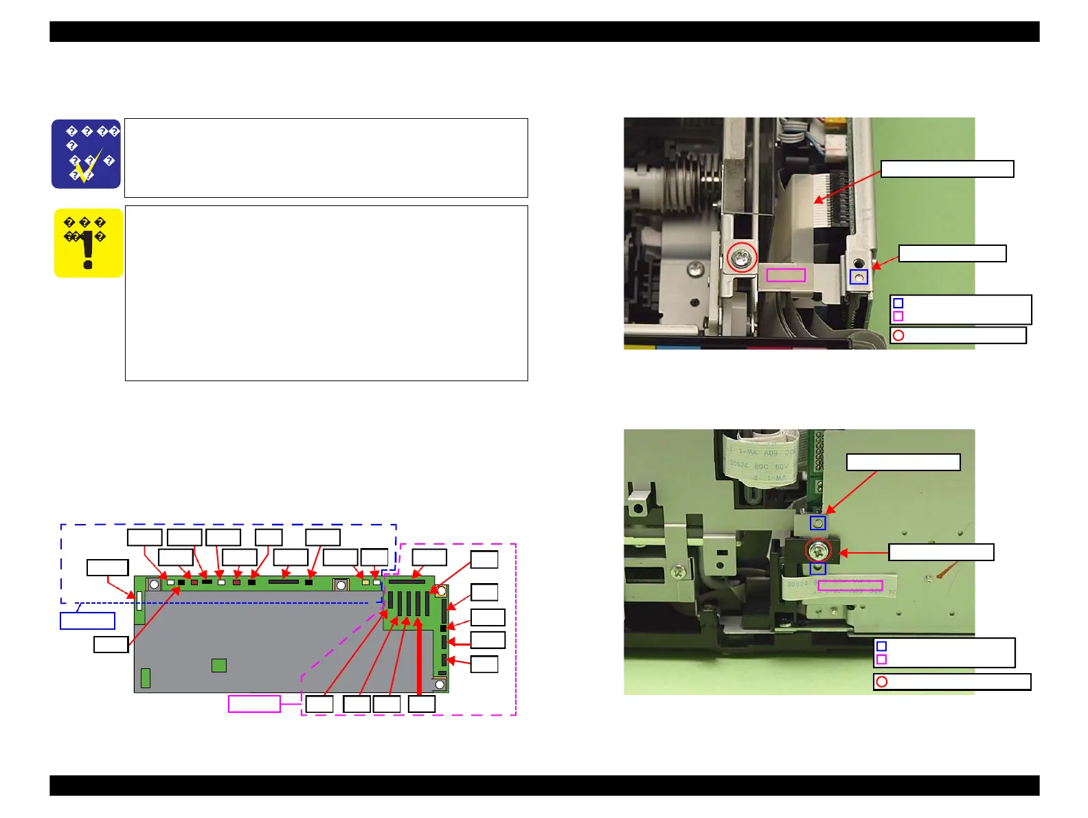
1.
Disconnect all the cables and FFCs connected to the section A on the Main
Board. (See "Connectors on the Main Board" (p. 117).)
Figure 4-229. Connector positions on the Main Board
2.
Remove the screw (x1) that secures the Grounding Plate M/B, and remove the
Grounding Plate M/B together with the Grounding Plate Sheet M/B.
Figure 4-230. Removing the Grounding Plate M/B
3.
Remove the screw that secures the Ferrite Core Holder A, and remove the
Ferrite Core Holder A.
Figure 4-231. Removing the Ferrite Core Holder A
The disassembly/reassembly procedures for Artisan 800/PX800FW/
TX800FW differ from those of Artisan 700/PX700W/TX700W, see
4.2.3.2 "Main Board / Grounding Plate M/B" (p117) for the
procedures.
When printing the CDR, the CDR Tray feed amount is adjusted
with compensation depending on the deterioration of the CDR
Tray, and the correction level is determined by the number of
printed CDRs. If the data on the EEPROM can not be copied when
replacing the Main Board, banding may occur while printing CDR
due to improper corrections caused because the data of the number
of printed CDRs can not be transferred.
When this happens, replace the CDR Tray Assy with a new one
together with the Main Board. (See
CN8 CN10
CN41 CN12 CN9 CN33
Positioning hole & dowel
Double-sided tape
Grounding Plate Sheet M/B
Positioning hole & dowel
Double-sided tape
C.B.S.(P2) 3x8 (8±1Kgfcm)
 Loading...


