4.3
Disassembly/reassembly procedures specific
to Artisan 700/PX700W/TX700W
4.3.1
Removing the Housing
4.3.1.1
Scanner Unit (Artisan 700/PX700W/TX700W)
Parts/Components need to be removed in advance:
None
Removal procedure
1.
Open the Scanner Unit.
2.
Cut the harness cover clamp with a nipper as shown in Fig. 4-203, and remove
the Cable Cover.
3.
Slide the Cable Cover to the rear of the printer by pushing the point A of the Cable
Cover to release the hooks (x4) and ribs (x2), and remove the Cable Cover.
Figure 4-203. Removing the Cable Cover
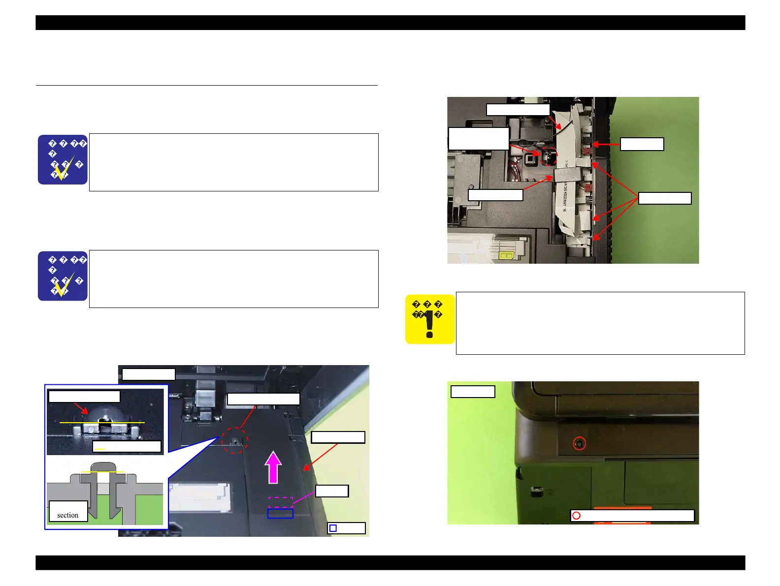
4.
Peel off the Scanner FFC (x3) together with the Ferrite core (x1) from the
Main Board.
5.
Pull out the terminal of the Grounding Wire from the Frame.
Figure 4-204. Removing the Scanner Unit (1)
6.
Remove the screw (x1) that secures the Scanner Unit.
Figure 4-205. Removing the Scanner Unit (2)
The disassembly/reassembly procedures for Artisan 800/PX800FW/
TX800FW differ from those of Artisan 700/PX700W/TX700W, see
4.2.2.2 "Scanner Unit" (p103) for the procedures.
The harness cover clamp needs to be cut when removing and cannot
be reused. When installing the Cable Cover, replace it with a new
one. (See Fig. 4-2)
Do not open/close the Scanner Unit with the screws that secure the
unit removed to avoid damage of the Scanner Unit Hinge.
 Loading...


