Epson Artisan 800/Epson Stylus Photo PX800FW/TX800FW/Epson Artisan 700/Epson Stylus Photo PX700W/TX700W
Disassembly Procedures
https://www.manualsbooks.com
4.Remove the screws (x5) that secure the Rear Frame and the screws (x2) that
secure the CR Motor Holder, and remove the Rear Frame together with the
CR Motor Holder. (See Fig. 4-127, Fig. 4-145.)
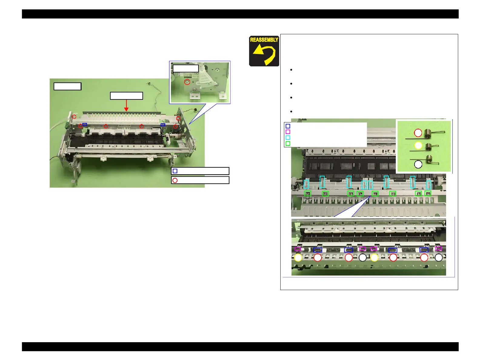
Figure 4-145. Removing the Rear Frame (2)
Align the ribs (x2) of the Rear Frame with the positioning holes
(x2) of the Main Frame. (See Fig. 4-145.)
Take care of the following points when installing the Torsion
Spring A, B and C.
Attach the Torsion Spring A (x4) to the ribs of the Main
Frame.
Attach the Torsion Spring B (x2) and C (x2) to the ribs of the
Rear Frame.
Align and attach the straight legs of the springs to the groove of
the Upper Paper Guide L/R.
Attach the hook-shaped legs to the hooks of the Rear Frame.
Figure 4-146. Attaching the Torsion Spring
Groove of the Upper Paper Guide L/R
Hook of the Rear Frame
 Loading...


