Epson Artisan 800/Epson Stylus Photo PX800FW/TX800FW/Epson Artisan 700/Epson Stylus Photo PX700W/TX700W
Disassembly Procedures
https://www.manualsbooks.com
Attach the Grounding Plate A between the Main Frame and
Base Frame. (See Fig. 4-106, Fig. 4-107.)
When installing the Grounding Plate B, attach the hook of it to
the hole of the Base Frame, and place it over the Main Frame.
(See Fig. 4-106, Fig. 4-107.)
Figure 4-107. Attaching the Grounding Plate
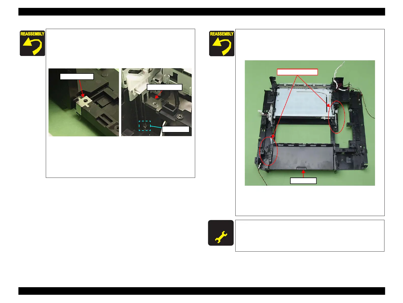
Align the positioning holes (x6) of the Main Frame with the
dowels (x6) of the Base Frame. (See Fig. 4-106)
Tighten the screws in the order shown in Fig. 4-106.
For routing the cables, see 4.4 "Routing FFC/cables" (p202).
When installing the Main Frame, be careful not to let it hit the
Base Frame. If the EJ Release Frame Assy L hits the Base
Frame (see Fig. 4-113
), the gear will come off, which may cause
Figure 4-108. Installing the Main Frame
Tighten the screws in the order shown in Fig. 4-106.
For routing the cables, see 4.4 "Routing FFC/cables" (p202).
After removing the Main Frame, make the specified adjustments.
(See Chapter 5 "ADJUSTMENT".)
 Loading...


