Epson Artisan 800/Epson Stylus Photo PX800FW/TX800FW/Epson Artisan 700/Epson Stylus Photo PX700W/TX700W
Disassembly Procedures
https://www.manualsbooks.com
5.
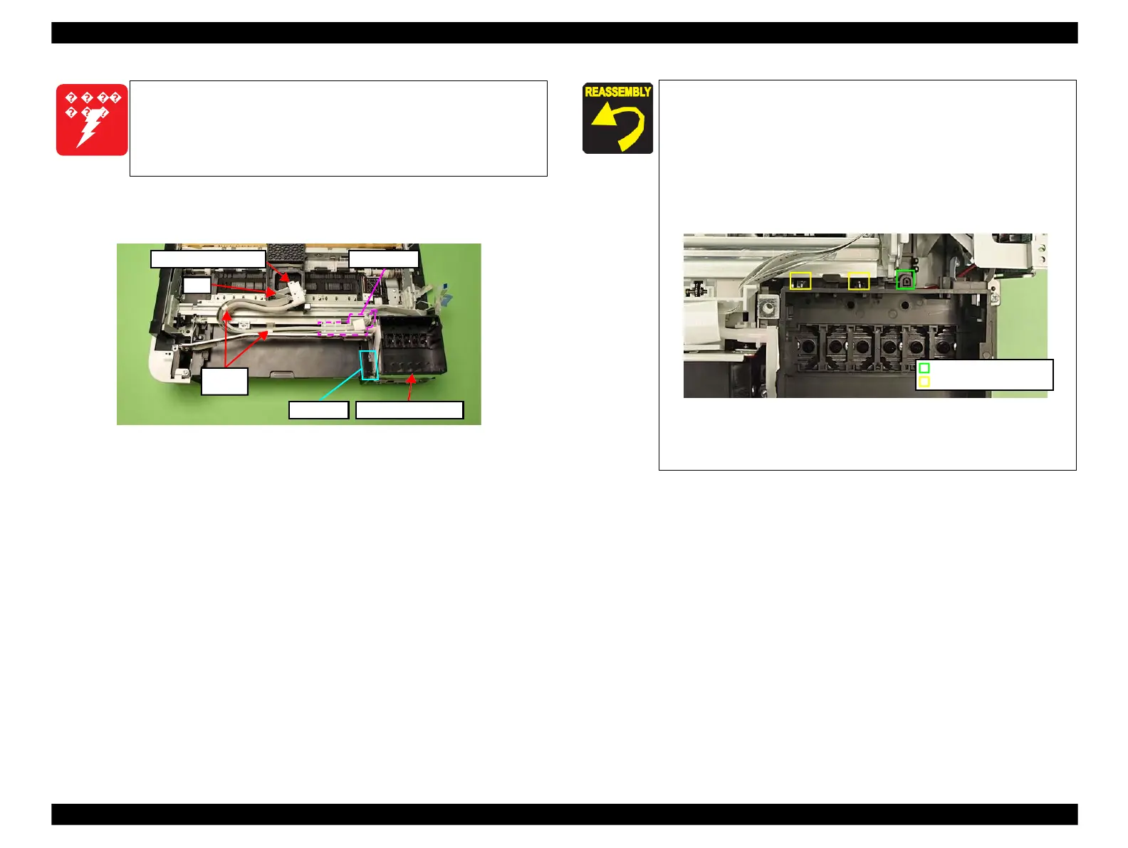
Release the Clamp Tubes (x2). (See Fig. 4-79.)
6.
Release the Ink Supply Tube Assy and FFC from the FFC Holder, and remove
the Ink Supply IC Holder Assy.
Figure 4-79. Removing the Ink Supply Tube Assy
To prevent ink leakage, make sure not to separate the Ink Supply
Tube Assy and the Cartridge Box Unit by removing the screws (x2)
on the section A shown in
Fig. 4-79. Loosening the screws on the
section A even just once will cause ink leakage, therefore, make sure
to replace the Ink Supply IC Holder Assy with a new one.
Make sure to insert the decompression tube into the socket on
the Cartridge Box Unit to the full to its base. (See Fig. 4-71.)
Make sure to align the positioning hole (x1) on the Cartridge
Box Unit with the dowel (x1) of the Base Frame when
reassembling them. (See Fig. 4-80.)
When installing the Cartridge Box Unit, make sure to secure
the hooks (x2) on the Main Frame to their positioning holes
(x2). (See Fig. 4-80.)
Figure 4-80. Installing the Cartridge Box Unit
Make sure to attach the grounding plate to the place shown in
Fig. 4-78, and secure it with the screw.
Positioning hole & dowel
Positioning hole & hook
 Loading...


