Foundry Configuration Guide for the FESX, FSX, and FWSX
8 - 10 © Foundry Networks, Inc. December 2005
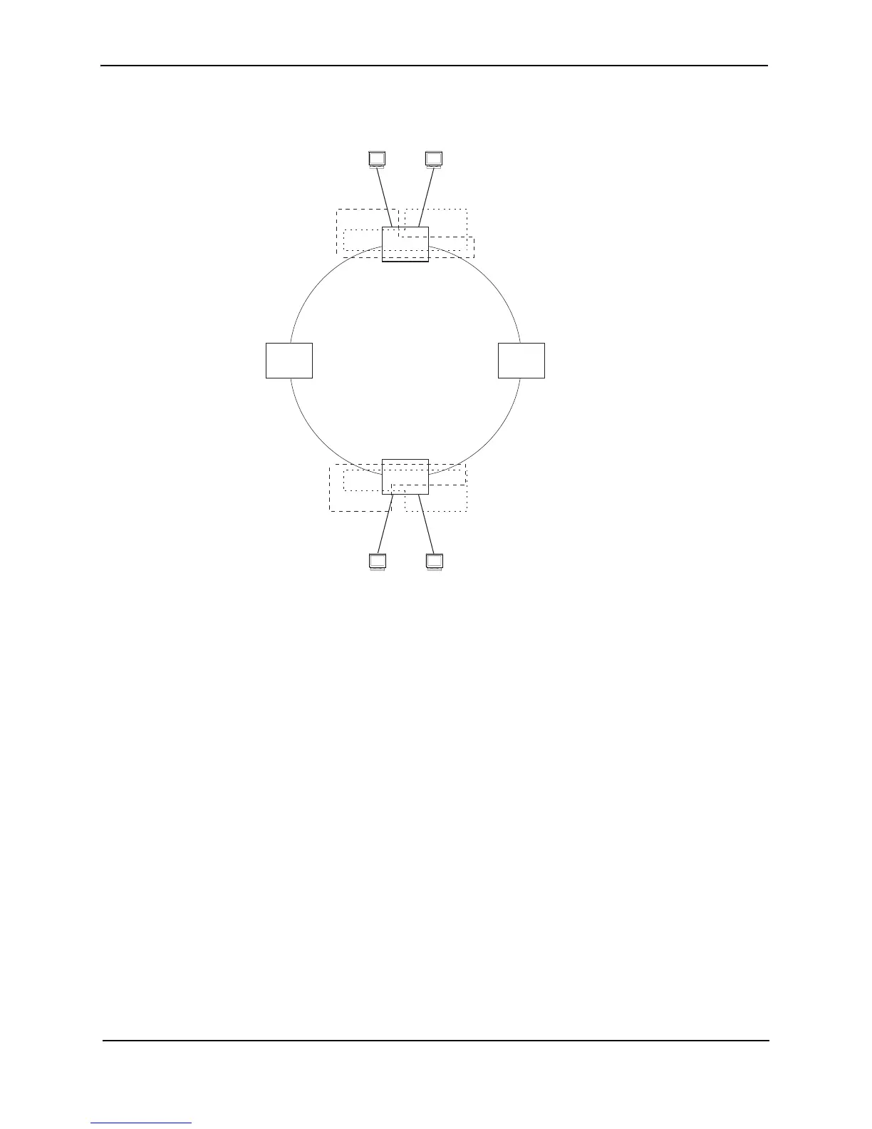
Figure 8.6 Metro ring – ring VLAN and customer VLANs
Notice that each customer has their own VLAN. Customer A has VLAN 30 and Customer B has VLAN 40.
Customer A’s host attached to Switch D can reach the Customer A host attached to Switch B at Layer 2 through
the ring. Since Customer A and Customer B are on different VLANs, they will not receive each other’s traffic.
You can configure MRP separately on each customer VLAN. However, this is impractical if you have many
customers. To simplify configuration when you have a lot of customers (and therefore a lot of VLANs), you can
use a topology group.
A topology group enables you to control forwarding in multiple VLANs using a single instance of a Layer 2 protocol
such as MRP. A topology group contains a master VLAN and member VLANs. The master VLAN contains all the
configuration parameters for the Layer 2 protocol (STP, MRP, or VSRP). The member VLANs use the Layer 2
configuration of the master VLAN.
In Figure 8.6, VLAN 2 is the master VLAN and contains the MRP configuration parameters for ring 1. VLAN 30
and VLAN 40, the customer VLANs, are member VLANs in the topology group. Since a topology group is used, a
single instance of MRP provides redundancy and loop prevention for both the customer VLANs.
If you use a topology group:
• The master VLAN must contain the ring interfaces. The ports must be tagged, since they will be shared by
multiple VLANs.
• The member VLAN for a customer must contain the two ring interfaces and the interfaces for the customer.
Since these interfaces are shared with the master VLAN, they must be tagged. Do not add another
customer’s interfaces to the VLAN.
For more information about topology groups, see “Topology Groups” on page 8-1.
See “MRP CLI Example” on page 8-16 for the configuration commands required to implement the MRP
configuration shown in Figure 8.6.
port 4/1
Switch D
port 1/1port 1/2
Switch B
Customer B
VLAN 40
port 2/1
Customer A
VLAN 30
Switch B
======
ring 1
interfaces 1/1, 1/2
topology group 2
master VLAN 2 (1/1, 1/2)
member VLAN 30 (1/1, 1/2, 2/1)
member VLAN 40 (1/1, 1/2, 4/1)
port 4/1
port 1/1port 1/2
Customer B
VLAN 40
port 2/1
Customer A
VLAN 30
Switch D
======
ring 1
interfaces 1/1, 1/2
topology group 2
master VLAN 2 (1/1, 1/2)
member VLAN 30 (1/1, 1/2, 2/1)
member VLAN 40 (1/1, 1/2, 4/1)