Configuring FSRP
December 2000 22 - 11
11. Repeat the steps above for each interface that is to be a redundant link. In this example, you would also need
to configure interface B for router 1 and interfaces C and D for router 2.
12. Click the Add button to apply the changes to the device’s running-config file.
13. Select the Save
link at the bottom of the dialog, then select Yes when prompted to save the configuration
change to the startup-config file on the device’s flash memory.
Configuring FSRP on Virtual Interfaces
A virtual interface will by default remain active until all underlying links go down. If you want the virtual link to go to
FSRP standby state when a subset of the ports goes down, you need to configure track ports.
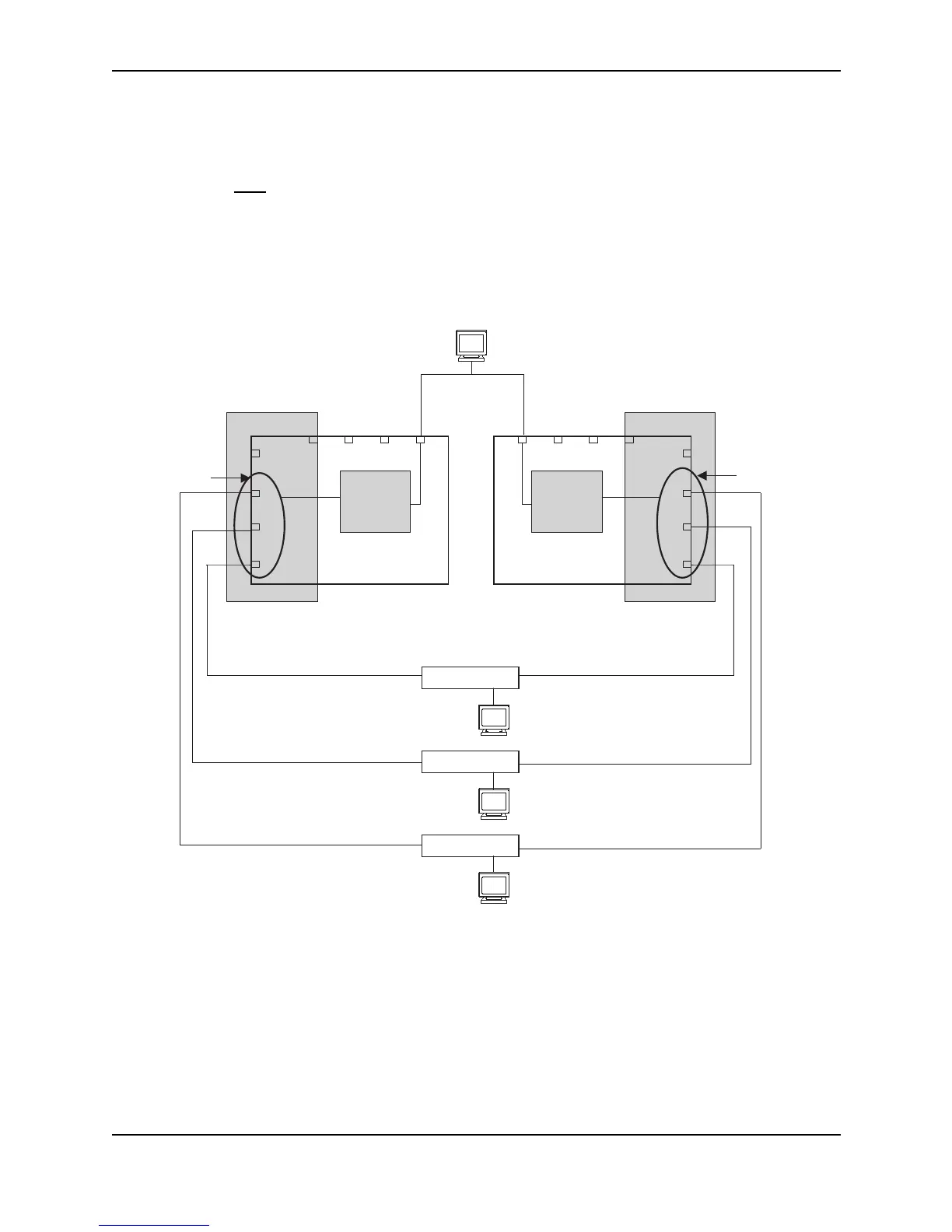
Figure 22.6 Configuring FSRP on virtual interfaces
Configuring Multiple Track Ports for Virtual Interfaces
In Figure 22.6, NetIron1 is the active router and NetIron2 the standby router for all active FSRP interfaces.
Suppose you want NetIron1 to go into the FSRP standby state and establish NetIron2 as the active router in case
ports 1, 2, 3, or 8 on NetIron1 go down. To do so, you would configure track ports for ports 1, 2, 3, and 8 on
NetIron1.
4
5
7
6
1
2
3
8
Switch
Router
IP Subnet
VLAN
Virtual
Interface 1
192.147.201.1
NetIron1
(ACTIVE)
4
8
6
7
1
2
3
5
Switch
Router
IP Subnet
VLAN
Virtual
Interface 1
NetIron 2
(STANDBY)
A
A
192.147.200.1
192.147.201.2
192.147.200.2
S
S
Switch
Switch
192.147.200.51
Switch
192.147.200.52
Switch
192.147.200.50
PC2
PC3
PC4
PC1
192.147.201.50