MPC5200B Users Guide, Rev. 1
5-4 Freescale Semiconductor
MPC5200B Clock Domains
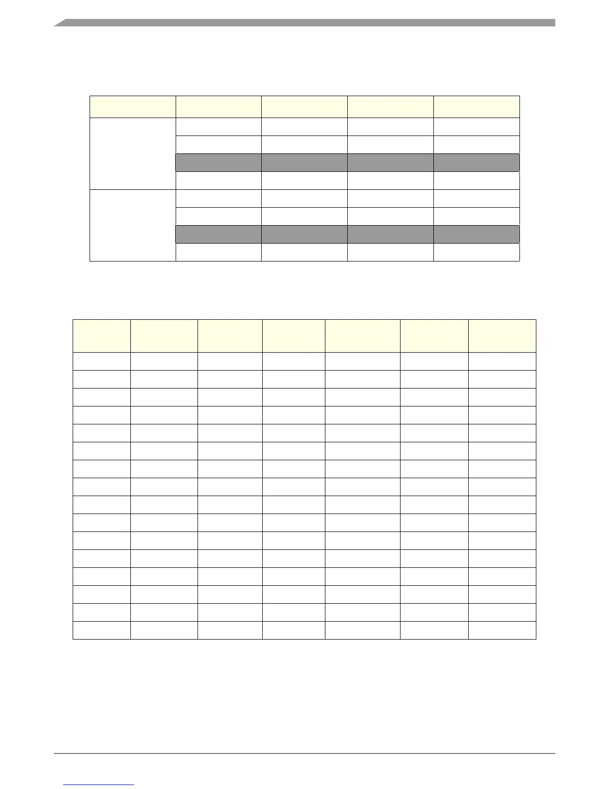
Table 5-2 shows the System PLL configuration and the corresponding fsystem frequencies for a 27.0 MHz and 33.0 MHz input clock.
Table 5-3 shows all possible clock ratios.
Table 5-2. System PLL Ratios
SYS_XTAL_IN sys_pll_cfg[1] sys_pll_cfg[0] f
VCOsys
[MHz] f
system
[MHz]
27.0
0 0 432.0 432.0
0 1 324.0 324.0
1
a
a
These are invalid configurations. The f
VCOsys
frequencies exceed the maximum operation frequency. See
MPC5200B Hardware Specification.
0 864.0 432.0
1 1 648.0 324.0
33.0
0 0 528.0 528.0
0 1 396.0 396.0
1
a
0 1056.0 528.0
1 1 792.0 396.0
Table 5-3. MPC5200B Clock Ratios
xlb_clk_sel XLB CLOCK ipb_clk_sel IPB CLOCK pci_clk_sel[1:0] PCI CLOCK
CLOCK Ratio
XLB:IPB:PCI
0f
system
/ 4 0 XLB 00 XLB 4:4:4
0f
system
/ 4 0 XLB 01 XLB/2 4:4:2
0f
system
/ 4 0 XLB 10 XLB/4 4:4:1
0f
system
/ 4 0 XLB 11 XLB/4 4:4:1
0f
system
/ 4 1 XLB /2 00 XLB/2 4:2:2
0f
system
/ 4 1 XLB /2 01 XLB/4 4:2:1
0f
system
/ 4 1 XLB /2 10 XLB/4 4:2:1
0f
system
/ 4 1 XLB /2 11 XLB/4 4:2:1
1f
system
/ 8 0 XLB 00 XLB 2:2:2
1f
system
/ 8 0 XLB 01 XLB/2 2:2:1
1f
system
/ 8 0 XLB 10 XLB/4 2:2:0.5
1f
system
/ 8 0 XLB 11 XLB/4 2:2:0.5
1f
system
/ 8 1 XLB /2 00 XLB/2 2:1:1
1f
system
/ 8 1 XLB /2 01 XLB/4 2:1:0.5
1f
system
/ 8 1 XLB /2 10 XLB/4 2:1:0.5
1f
system
/ 8 1 XLB /2 11 XLB/4 2:1:0.5