I
2
C Interface Registers
MPC5200B Users Guide, Rev. 1
Freescale Semiconductor 18-7
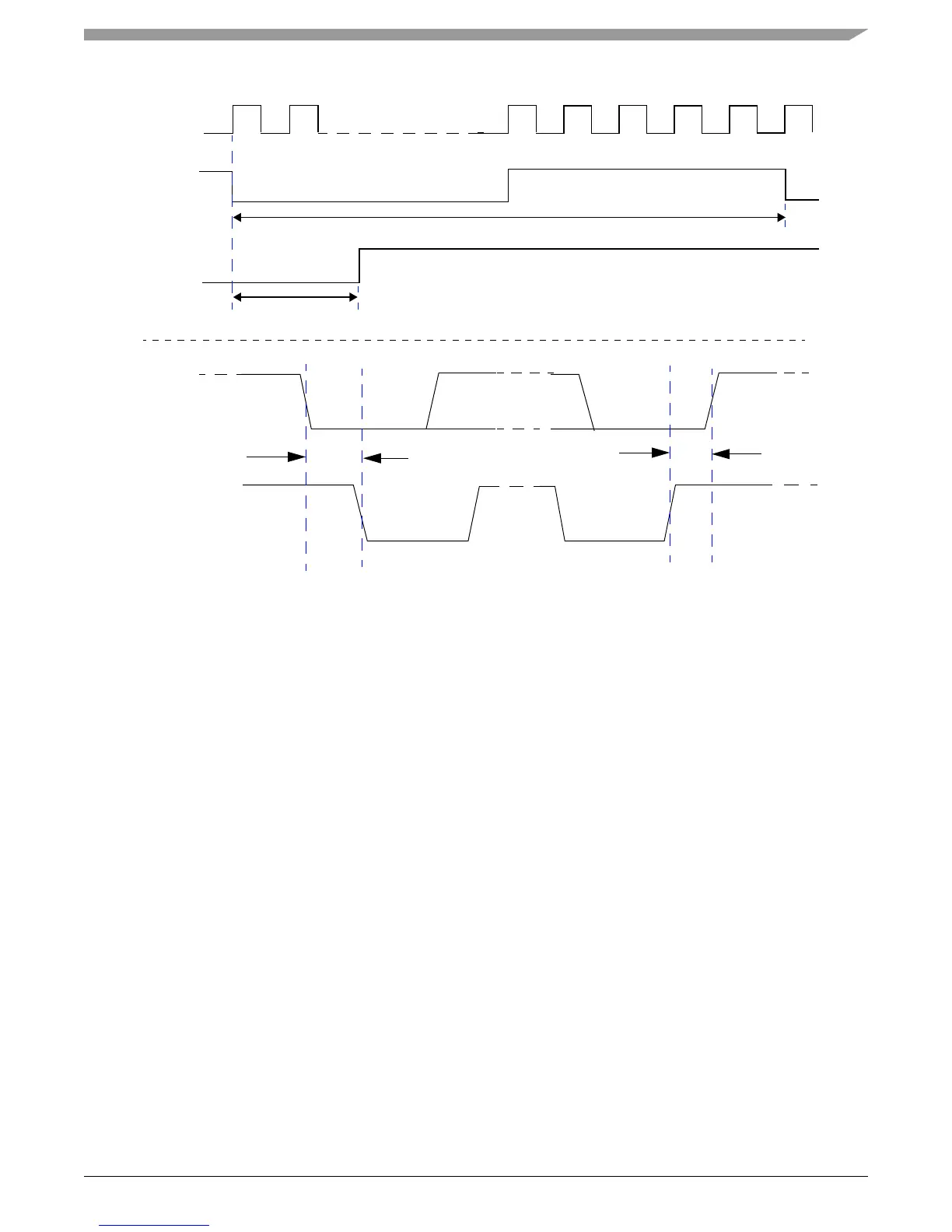
Timing Diagram—SCL Period and SDA Hold Time
Figure 18-8. Timing Diagram of I2C Signal Relationships
For standard mode I2C, the I2C specification states that
(SCL <= 100 kHz)
AND
(0.3 us <= SDA Hold Time <= 3.45 us)
AND
(SCL Hold of START >= 4 us)
AND
(SCL Hold of STOP >= 4 us)
which means that the system programmer must choose SCL Period, SDA Hold, SCL Hold of START, and SCL Hold of STOP from Table
18-4 to satisfy the following four equations (5) through (8):
SCL Period >= (1/100,000) * [system clock speed (in Hz) (5)
AND
(0.0003)*[SCL (in kHz)]*(SCL Period) <= SDA Hold <= (0.00345)*[SCL (in kHz)]*(SCL Period) (6)
AND
SCL Hold of START >= (0.004)*[SCL (in kHz)]*(SCL Period) (7)
AND
SCL Hold of STOP >= (0.004)*[SCL (in kHz)]*(SCL Period) (8)
In this case, the simplest strategy for the system programmer to follow is this:
System
Clock
SCL
SDA
SCL Period
SDA Hold
SDA
SCL
START condition STOP condition
SCL Hold of START
SCL Hold of STOP