ATA Bus Background
MPC5200B Users Guide, Rev. 1
Freescale Semiconductor 11-27
11.7.2 ATA Modes
11.7.3 ATA Addressing
In the ATA interface, there are two aspects of addressing that are present: register addressing and sector addressing. These are discussed in
the next sections.
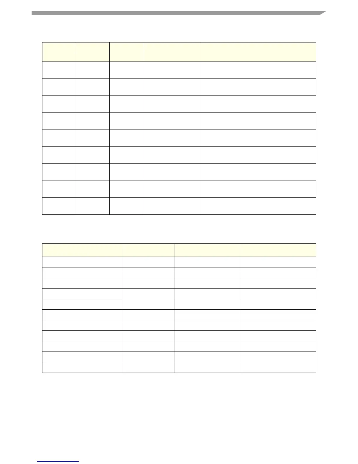
Table 11-35. ATA Standards
Interface
Standard
Standard
Type
PIO Modes DMA Modes
Special Features or Enhancements
introduced Relative to IDE/ATA
IDE/ATA ANSI 0,1,2 Single word—0,1,2
Multiword—0
—
ATA-2 ANSI 0,1,2,3,4 Single word—0,1,2
Multiword—0,1,2
Block transfers, logical block addressing,
improved identify drive command
FAST ATA Marketing 0,1,2,3 Single word—0,1,2
Multiword 0,1
Same as ATA-2
Fast ATA-2 Marketing 0,1,2,3,4 Single word—0,1,2
Multiword—0,1,2
Same as ATA-2
ATA-3 Unofficial 0,1,2,3,4 Single word—0,1,2
Multiword—0,1,2
Same as ATA-2, plus improved reliability, SMART
Ultra ATA Unofficial 0,1,2,3,4 Single word—0,1,2
Multiword—0,1,2,3
Same as ATA-3
ATAPI ANSI 0,1,2,3,4 Single word—0,1,2
Multiword—0,1,2
Support for non-hard-disk devices CD-ROM,
Tape drives, etc.
EIDE Marketing 0,1,2,3,4 Single word—0,1,2
Multiword—0,1,2
Same as ATA-2, plus ATAPI and dual host
adapters
ATA-4 ANSI 0,1,2,3,4 Multiword—0,1,2
Ultra DMA—0,1,2
Same as ATA-3, Single word DMA retired
Table 11-36. ATA Physical Level Modes
Mode Cycle Time (ns) Transfer Rate (MB/s) Standard
PIO mode 0 600 3.3ATA
PIO mode 1 383 5.2ATA
PIO mode 2 240 8.3ATA
PIO mode 3 180 11.1 ATA-2 (IORDY required)
PIO mode 4 120 16.7 ATA-2 (IORDY required)
DMA mode 0 (Multiword) 480 4.2ATA
DMA mode 1 (Multiword) 150 13.3ATA-2
DMA mode 2 (Multiword) 120 16.7ATA-2
Ultra DMA mode 0 114 16.7ATA-4
Ultra DMA mode 1 75 25 ATA-4
Ultra DMA mode 2 55 33 ATA-4