MPC5200B Users Guide, Rev. 1
21-6 Freescale Semiconductor
e300 Core JTAG/COP Serial Interface
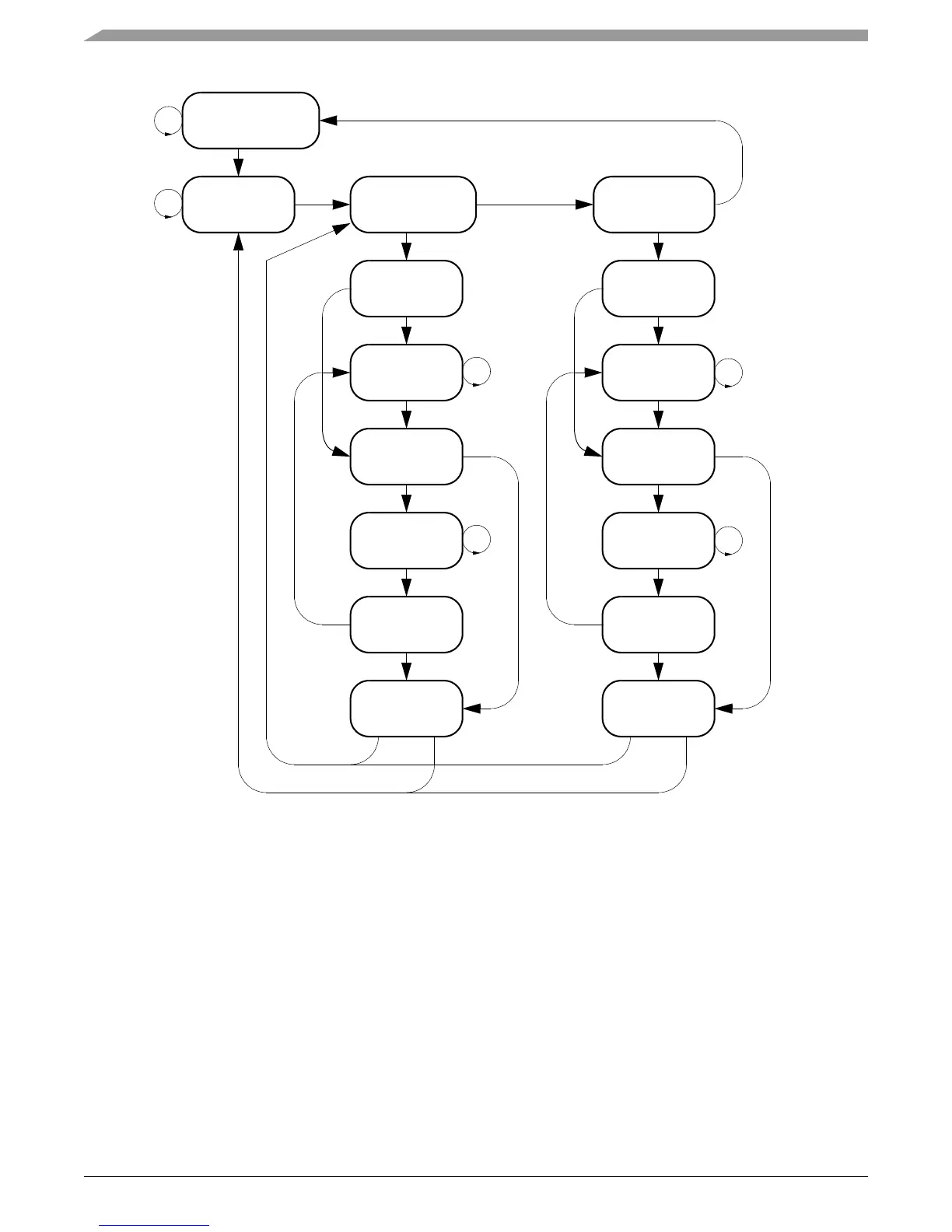
Figure 21-4. State Diagram—TAP Controller
Instructions are loaded by stepping the state machine to the Shift-IR state by applying an appropriate sequence of values on TMS at successive
rising edges of TCK. Once in the Shift-IR state, TMS is held low and appropriate values are applied at TDI (lsb-first) at successive rising
edges of TCK. As the last (ms) bit is applied at TDI, TMS is set high and the state machine is advanced through the Exit1-IR and Update-IR
states. The instruction becomes effective at the falling edge of TCK in the Update-IR state.
Data registers are loaded by first selecting the desired data register with an appropriate instruction, then stepping the state machine to the
Shift-DR state. Once in the Shift-DR state, TMS is held low and appropriate values are applied at TDI (lsb-first) at successive rising edges of
TCK. As the last (ms) bit is applied at TDI, TMS is set high and the state machine is advanced through the Exit1-DR and Update-DR states.
The data becomes effective at the falling edge of TCK in the Update-DR state.
21.6 e300 Core JTAG/COP Serial Interface
The Common On-chip Processor (COP) external interface adheres to the IEEE 1149.1 serial protocol. The COP uses the JTAG interface which
includes a TAP Controller, a COP Controller, input and output multiplexors, registers, several shift register latches (SRLs) and a counter
(RunN) which controls clock execution. All IEEE 1149.1 public instructions are implemented (SAMPLE_PRELOAD, BYPASS, and
EXTEST). Figure 21-5 shows the components that make up the microprocessor JTAG/COP serial interface.
Test-Logic-Reset
Run-Test/Idle Select-DR Scan Select-IR Scan
Capture-DR Capture-IR
Shift-DR Shift_IR
Exit1-DR Exit1-IR
Pause-IRPause-DR
1
0
0
111
0
0
0
1
1
0
0
0
11
1
1
0
0
1
0
11
1
0
0
0
110 0
Exit2-DR
Update-DR Update-IR
Exit2-IR