ATA Interface Description
MPC5200B Users Guide, Rev. 1
Freescale Semiconductor 11-25
NOTE
MPC5200B provides the ATA_ISOLATION output signal. This signal is shared with the A22 output
of the LocalPlus Most/Graphics mode.
The ATA_ISOLATION is not a signal defined by the ATA Standard. It is provided to support an external ATA transceiver. ATA_ISOLATION
is an active high signal to control external transceiver devices and to ‘isolate’ the ATA bus from the LocalPlus (shared) bus.
It can force the transceiver direction "MPC5200B -> disk drive". Only during an ATA read is this signal allowed to go low, forcing tranceiver
direction "disk drive ->MPC5200B".
The ATA_ISOLATION should be connected to the Direction input of the transceiver.
• High = Write to drive
• Low = Read from drive
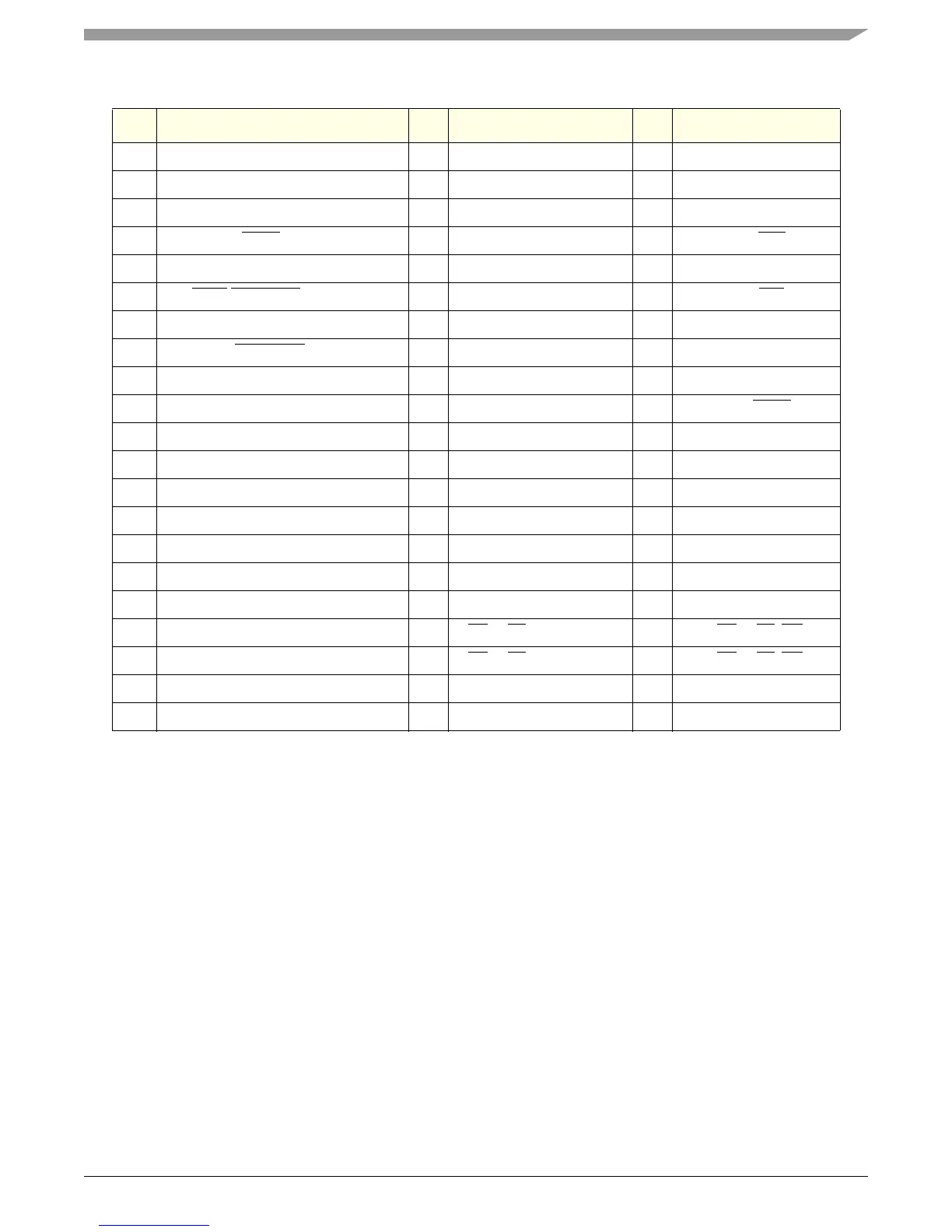
20 KEY — No Signal:Alignment key — —
2 DMARQ I DMARQ:DMA Request I ATA_DRQ
22 GND ————
23 DIOW
:STOP O DIOW O ATA_IOW
24 GND ————
25 DIOR:HDMARDY:HSTROBE O DIOR O ATA_IOR
26 GND ————
27 IORDY:DDMARDY:DSTROBE I IORDY I ATA_IOCHRDY
28 CSEL — NC — —
29 DMACK O DMACK O ATA_DACK
30 GND ————
31 INTRQ I INTRQ I ATA_INTRQ
32 Reserved — — — —
33 DA[1] O DA[1]:Address Bus Bit1 O ATA_SA[1]
34 PDIAG — NC — —
35 DA[0] O DA[0]:Address Bus Bit0 O ATA_SA[0]
36 DA[2] O DA[2]:Address Bus Bit2 O ATA_SA[2]
37 CS[0] O CS[1]FX:Chip Select 0 O ATA_CS[1]FX(CS[4])
38 CS[1] O CS[3]FX:Chip Select 1 O ATA_CS[3]FX(CS[5])
39 DASP — NC — —
40 GND ————
Table 11-34. ATA Controller External Connections (continued)
Pin# Cable I/O System Board I/O MPC5200B