PSC Operation Modes
MPC5200B Users Guide, Rev. 1
Freescale Semiconductor 15-47
After the stop bits are sent, if no new character is in the Tx holding register, the TxD output remains high (mark condition) and the Tx empty
bit, SR[TxEMP], is set. Transmission resumes and TxEMP is cleared when the CPU loads a new character into the PSC Tx buffer (TB).
• If the transmitter receives a disable command, it continues until any character in the Tx shift register is completely sent.
• If the transmitter is reset through a software command, operation stops immediately.
• If the clear-to-send operation is enabled, CTS
must be asserted for the character to be transmitted.
• If CTS
is negated in the middle of a transmission, the character in the shift register is sent and TxD remains in mark state until CTS
is reasserted.
• If the transmitter is forced to send a continuous low condition by issuing a send break command, the transmitter ignores the state of
CTS
.
• If the transmitter is programmed to automatically negate RTS
when a message transmission completes, RTS must be asserted
manually before a message is sent.
In applications in which the transmitter is disabled after transmission is complete and RTS is appropriately programmed, RTS is negated one
bit-time after the character in the shift register is completely transmitted. The transmitter must be manually re-enabled by reasserting RTS
before the next message is to be sent.
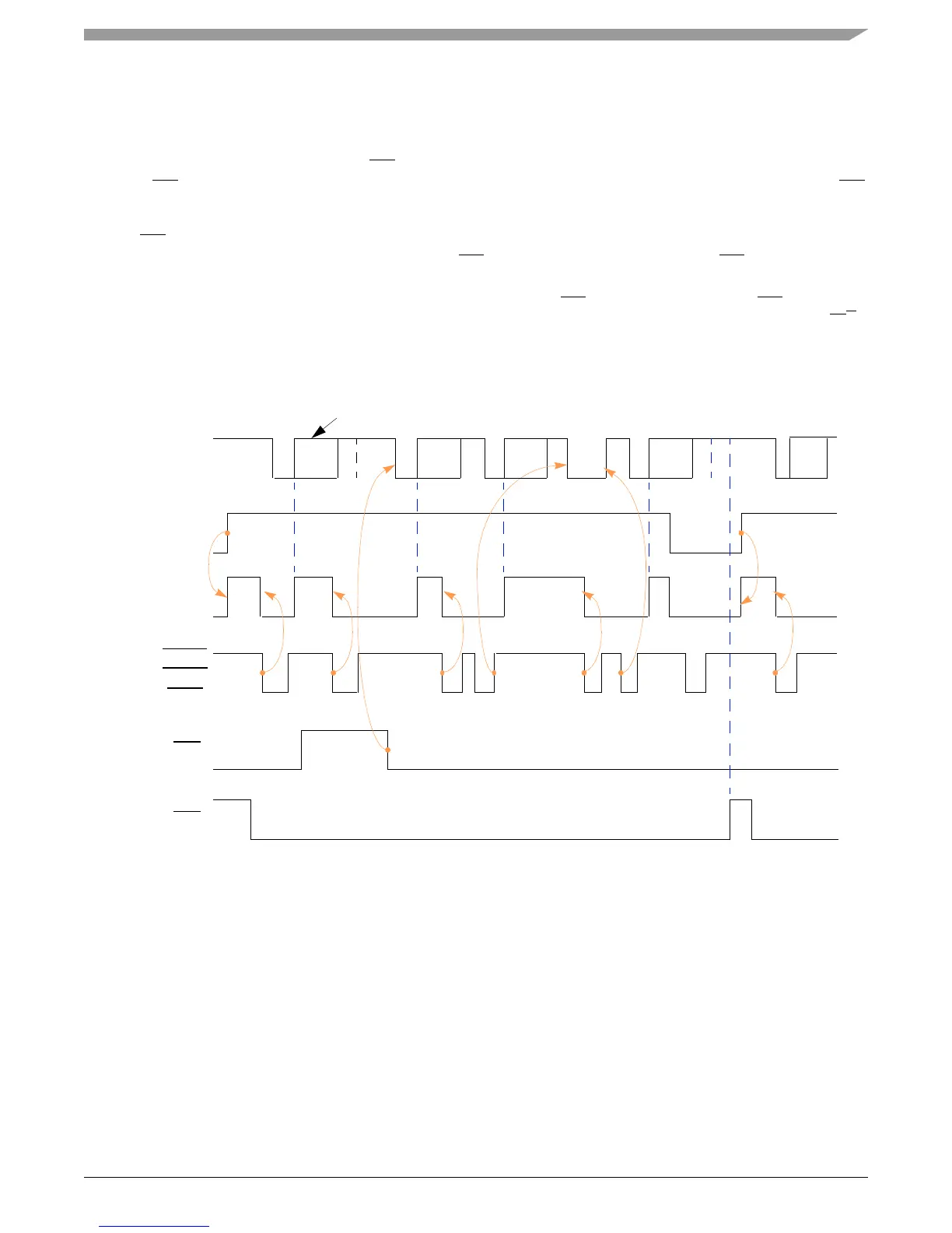
Figure 15-4 shows the transmitter functional timing information.
Figure 15-4. Timing Diagram—Transmitter
15.3.1.4 Receiving in UART Mode
After a hardware reset, all PSCs are in UART mode. The receiver is enabled through its CR, as described in Section 15.2.5, Command Register
(0x08)—CR. Figure 15-5 shows the receiver functional timing.
C1
1
C2 C3 Break
C4 C6
TxD
Transmit
Enabled
SR [TxRDY]
W
2
WWW WWWW
CTS
3
RTS
4
Manually asserted
by
BIT
-
SET
command
Manually
asserted
Start
break
C5
not
transmitted
C6C4 Stop
break
C3C2C1
1
C1 in transmission
internal
module
select
NOTE:
1. Cn = transmit characters
2. W = write
3. MR2[TxCTS] = 1
4. MR2[TxRTS] = 1