MPC5200B Users Guide, Rev. 1
2-30 Freescale Semiconductor
Pinout Tables
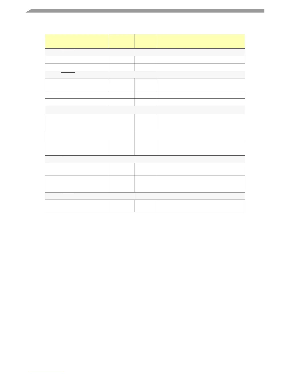
Table 2-8. LocalPlus Dedicated Signals
PIN / BALL NUMBER Function
Reset
Value
Description
Pin LP_RW Ball W16
LocalPlus Read/Write logic 1 LocalPlus Read/Write LIne
Reset Configuration RST_CFG3 logic 1 Bit 3 -- ppc_pll_cfg_1
Pin LP_ALE Ball V14
LocalPlus Address
Latch Enable
logic 1 LocalPlus Address Latch Enable for Multiplexed
Transitions
MOST Graphics A23 logic 1 MOST Graphics Address Bit A23
Reset Configuration RST_CFG4 logic 1 Bit 4 ppc_pll_cfg_0
Pin LP_ACK Ball U14
LocalPlus LP
Acknowledge
logic 1 Acknowledge signal for LP peripherals.
Acknowledge signal for Large Flash or MOST
Graphics, if bursts are not enabled.
LFLASH BRST logic 1 BURST indication for Large Flash, if bursts are
enabled
MOST Graphics BRST logic 1 BURST indication for MOST Graphics, if bursts are
enabled
Pin LP_TS Ball Y13
LocalPlus LP Transfer
Start
logic 1 LocalPlus Transfer Start
Reset Configuration 5 RST_CFG5 logic 1 Bit 5 -- xlb_clk_sel
bit = 0: XLB_CLK = f
system
/ 4
bit = 1: XLB_CLK = f
system
/ 8
Pin LP_OE Ball D08
LocalPlus LP Output
Enable
logic 1 LocalPlus Output Enable