▶
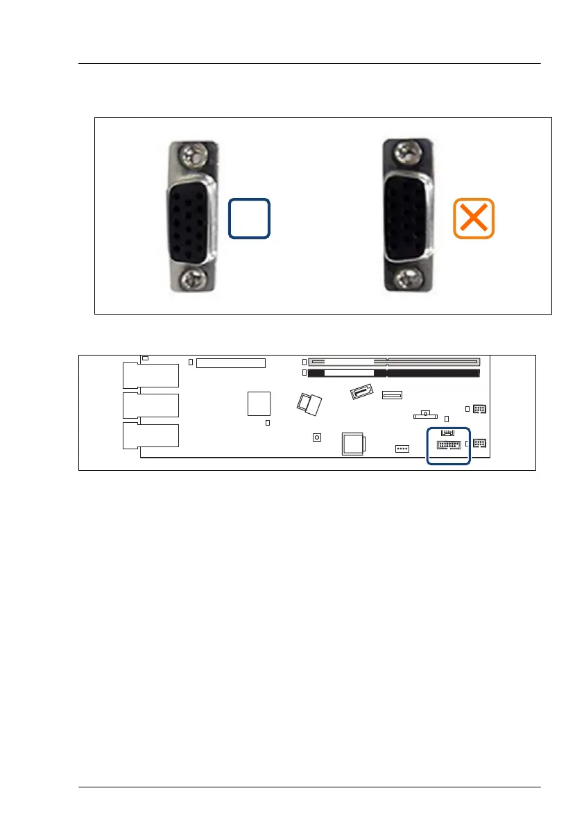
Insert the front VGA cable from the server inside through the opening.
▶
Fasten the front VGA connector with the two screws (see circles).
Slot 1
external connectors
LAN 1
Management
LAN
Shared LAN 1
DIMM 2B
DIMM 1B
Micro
SD
iRMC
S6
ROC
INDICATE
CSS
SATA
ODD
Front VGA
SMBSYS
USB 5
SATA
0-3
LAN 2
FAN1
SYS
FAN2
SYS
Battery
Figure 219: Connecting the front VGA cable
▶
Connect the front VGA cable to the system board connector "Front VGA".
Concluding steps
▶
"Installing the air duct" on page
66.
▶
"Reassembling" on page
53.
▶
"Connecting the power cord" on page 57.
▶
"Switching on the server" on page 60.
▶
If applicable, "Installing the front cover with lock" on page 61.
Front panel
RX1330 M5 Upgrade and Maintenance Manual 273

 Loading...