▶
Remove the protective plastic cover from the CPU socket of the new system
board and fit it onto the socket of the defective system board which will be
sent back to spares.
Returned system boards without this cover probably have to be
scrapped.
▶
Remove the TPM, see "Removing the TPM" on page 301.
Installing the new system board
▶
Confirm that the CPU model number printed on the top of the CPU fits with
the requirements.
▶
Install the CPU on the new system board, see "Installing the CPU" on
page 235.
▶
Check the settings on the new system board, see "Onboard settings" on
page
360.
▶
Install the heat sink, see "Installing the heat sink" on page 240.
▶
Insert the system board by holding it at a slight angle. Slide the connectors
into the I/O panel.
▶
Lower the system board carefully into the chassis.
▶
Adjust the system board. If necessary adjust the position of the system
board with a gentle twisting motion (orange circles in Figure 260 show the
centering bolts).
▶
Fasten the system board with eight screws, see Figure 260.
▶
Connect all cables to the system board.
For the cable plans, see "Appendix B" on page 363.
Concluding steps
▶
If applicable, install the TPM, see "Installing the TPM" on page 296.
▶
If applicable, install the Dual microSD 64GB Enterprise, see "Installing the
Dual microSD 64GB Enterprise" on page 320.
▶
If applicable, install all M.2 SSDs, see "Installing the M.2 SSD" on page 313.
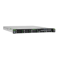
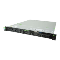
System board and components
RX1330 M5 Upgrade and Maintenance Manual 333

 Loading...