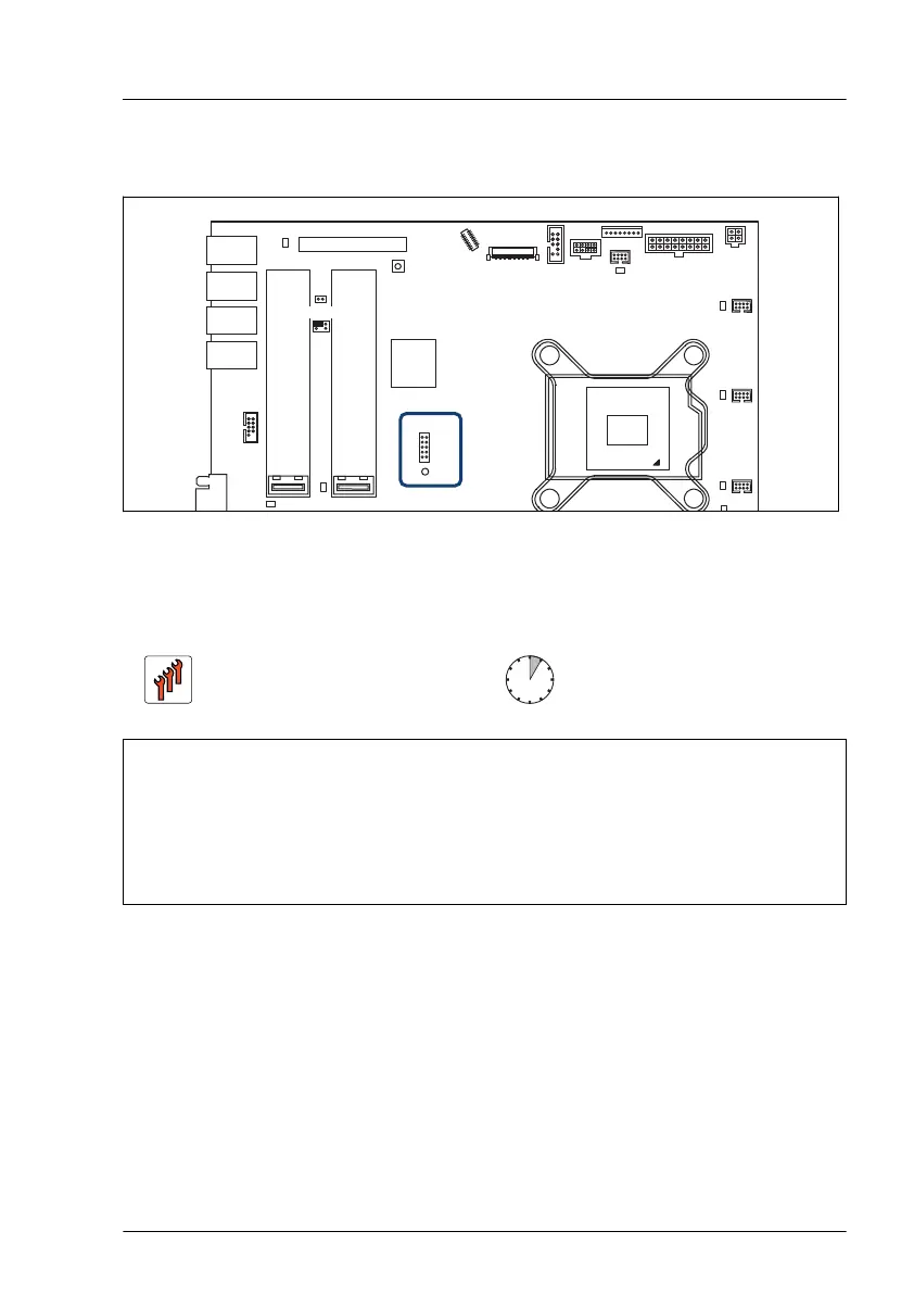
15.4.2 Position of the TPM
USB 2.0
USB 2.0
USB 3.2
Gen 2
SSD1
M.2
M.2
SSD2
TPM
Slot 3
JP3
PWR1
FRONT
PWR2
P30
PC98
SERIAL
Intel
C256
USB 3.2
Gen 2
FAN3
SYS
FAN4
SYS
FAN5
SYS
FAN6
SYS
ODD
PWR
PANEL
TYPE C
FRONT
JP2 JP1
Clear RTC
Figure 238: Position on the system board
15.4.3 Installing the TPM
Field Replaceable Unit
(FRU)
Hardware: 5 minutes
Software: 5 minutes
Tools: – Bit screw driver
–
TPM bit insert
(*)
(*)
For Japan:
– TPM module fixing tool (S26361-F3552-L909)
Preliminary steps
▶
"Suspending BitLocker functionality" on page 69
.
▶
If applicable, "Removing the front cover with lock" on page 45.
▶
"Shutting down the server" on page 46.
▶
"Disconnecting the power cord" on page 47.
▶
"Getting access to the component" on page 49.
System board and components
RX1330 M5 Upgrade and Maintenance Manual 295

 Loading...