13.4 Front VGA
13.4.1 Positions of the front VGA module
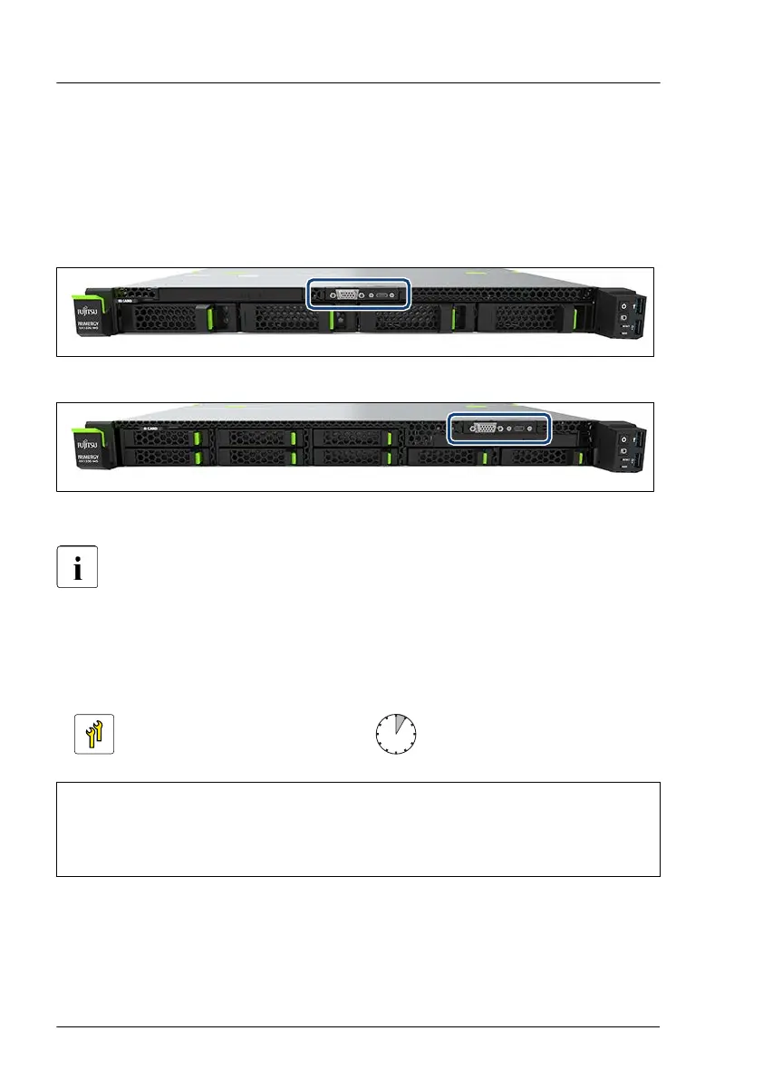
Some configurations of
fer a front VGA module.
Figure 206: Position of the front VGA module - example 3.5-inch HDD configuration
Figure 207: Position of the front VGA module - example 2.5-inch HDD configuration
The installation bay of the front VGA module depends on the 2.5-inch or
3.5-inch HDD configuration. The proceeding for installing/removing is
identic.
13.4.2 Installing the front VGA in the front VGA module
Upgrade and Repair Unit
(URU)
Hardware: 5 minutes
Tools: – flat screw driver (for break out)
– Phillips PH2 / (+) No. 2 screw driver
– hexagon screw driver 5 mm
Front panel
264 Upgrade and Maintenance Manual RX1330 M5
 Loading...