GAMATRONIC ELECTRONIC INDUSTRIES LTD.
25
During this step, the LEDs are also checked sequentially.
3. Finally, the normal default screen is displayed.
LOAD LEVEL ---21:20:25---
L1:__________ 000A, 230V BATTERY: 864V
L2:__________ 000A, 230V UPS OK (ON)
L3:__________ 000A, 230V STSW OK (INV)
Figure 19: Default screen, with no load, for 3-phase output
IMPORTANT
NOTE: YOUR POWER+ SYSTEM HAS BEEN DELIVERED TO YOU WITH THE OUTPUT VOLTAGE AND
FREQUENCY SET TO MATCH YOUR REQUIREMENTS
. CHECK NOW TO VERIFY THAT THESE
SETTINGS ARE CORRECT
.
TO SET MODULE/S FREQUENCY, SEE SECTION 7.9.2 ON PAGE 86.
TO SET MODULE/S VOLTAGE, SEE SECTION 7.9.3 ON PAGE 87.
(If the voltage and frequency settings are correct, continue with section 3.5.1 below.)
3.5.1 Continue first-time startup
1. Switch all battery switches "ON" – on the UPS and on all battery cabinets, if any.
2. You can now turn on the load devices.
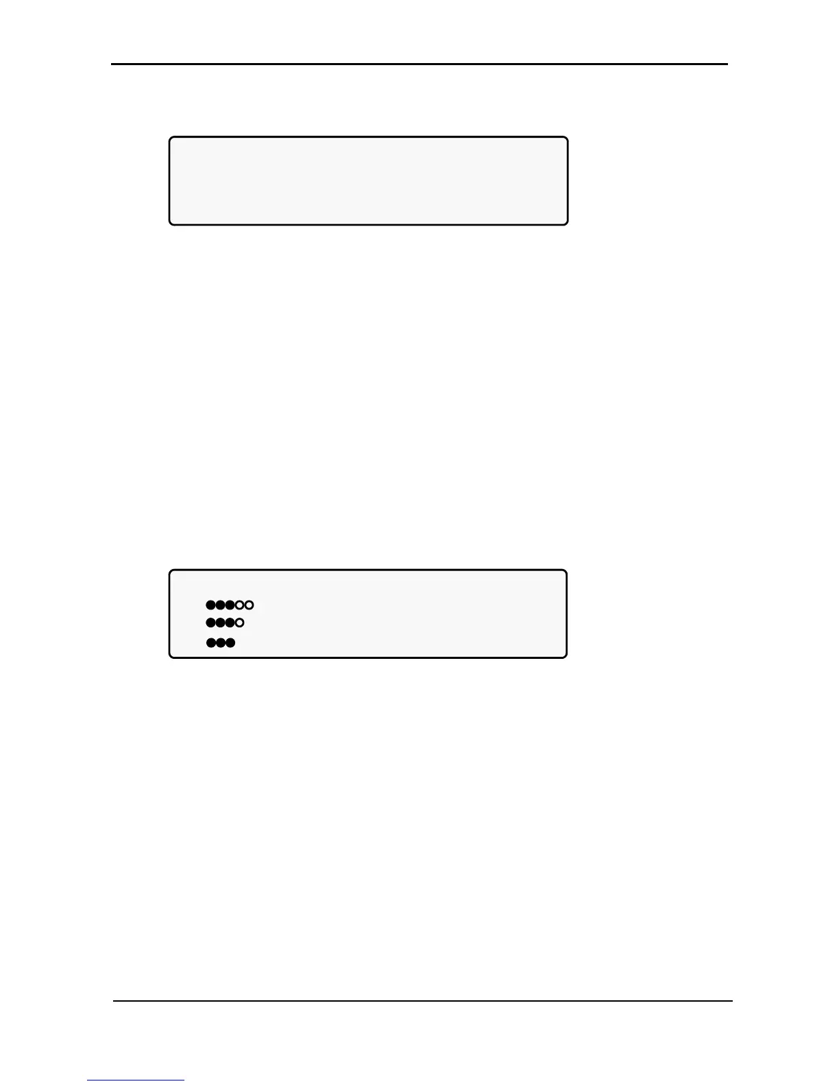
3. After turning on the load devices, verify that you have a normal reading on the display screen. The
display will look similar to Figure 20, but of course your readings will be different.
LOAD LEVEL ---11:20:25---
L1: _____ 015A, 230V BATTERY: 868V
L2: ______ 012A, 230V UPS OK (ON)
L3: _______ 011A, 230V STSW OK (INV)
Figure 20: Normal display, system under load (3-phase output)
Continue with section 3.6 on page 26.