GAMATRONIC ELECTRONIC INDUSTRIES LTD.
64
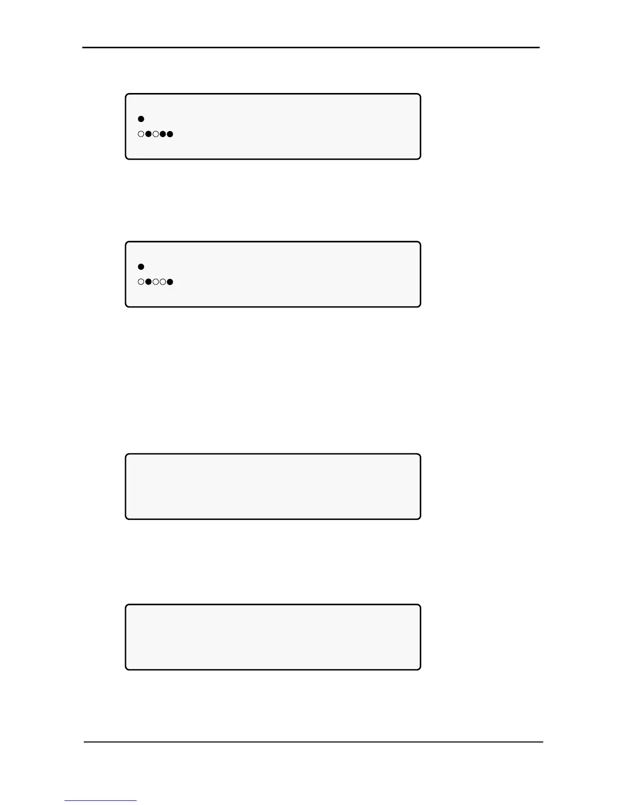
6. View the system jumper settings without remote panel:
[Main Menu > SYSTEM > ▼ ▼ ▼]
JMP: JMP1, JMP2, JMP3, JMP6 and JMP9
=IN 1. NOT HARD SILICON
2. SILICON MODE 6. NO RMT PAN.
12369 3. CAPACITY LOW 9. AC: 230V
Figure 88: Jumper settings WITHOUT remote panel
7. View the system jumper settings with remote panel:
[Main Menu > SYSTEM > ▼ ▼ ▼]
JMP: JMP1, JMP2, JMP3, JMP6 and JMP9
=IN 1. NOT HARD SILICON
2. SILICON MODE 6. Remote pan.
12369 3. CAPACITY LOW 9. AC: 230V
Figure 89: Jumper settings WITH remote panel
Note: In Figure 88 and Figure 89, “Silicon mode” indicates that the configuration jumper is installed, thus
allowing for modifications. “Hard Silicon” indicates that the factory defaults hard reset jumper is
installed. This is required only at the factory or whenever software reset fails. Refer to section
7.15.9.3 for a detailed description of jumpers.
8. View the internal controller voltages:
[Main Menu > SYSTEM > ▼ ▼ ▼ ▼]
5VDC : 5.19V CONTROLLER INTERNAL
12VDC: 12.01V VOLTAGES
5VP : GOOD
5V2 : GOOD -12VDC: GOOD
Figure 90: Internal controller voltages
9. View battery parameters:
[Main Menu > SYSTEM > ▼ ▼ ▼ ▼ ▼]
BATTERY CHARGE LEVEL: 010Ah 050%
WHILE TOTAL CAPACITY: 020Ah
REMAINING BACKUP: 0010 MINUTES
BATTERY TEMPERATURE: 12°C
Figure 91: Battery parameters
Note: The data displayed in Figure 91 depends on the options installed and configured. See Figure 157 on
page 90 and Figure 193 on page 101.