4.6 Status indicators
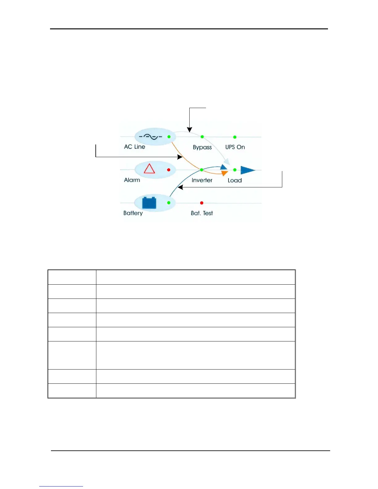
The status indicators show precisely what is running and how the UPS is providing power to the load.
The diagram below shows the power source and destination routes in use for each of the three automated
operation modes.
Figure 30: Status indicators
Table 5: Status indicators
Ac Line
Green – Shows that the ac input is present and within range
Alarm
Red – Flashes to indicate general alarm condition
Battery
Green – Shows that the battery is in discharge mode
Bypass
Green – Shows that the load is supplied from the ac input
Inverter
Green - Shows that the inverter is supplying power to the load
Bat. Test
Blinking Red – Shows that a battery test is in progress
Steady Red – Battery test failure
UPS On
Green – Indicates that the UPS is running
Load
Green – Indicates that ac voltage is available at the output