GAMATRONIC ELECTRONIC INDUSTRIES LTD.
72
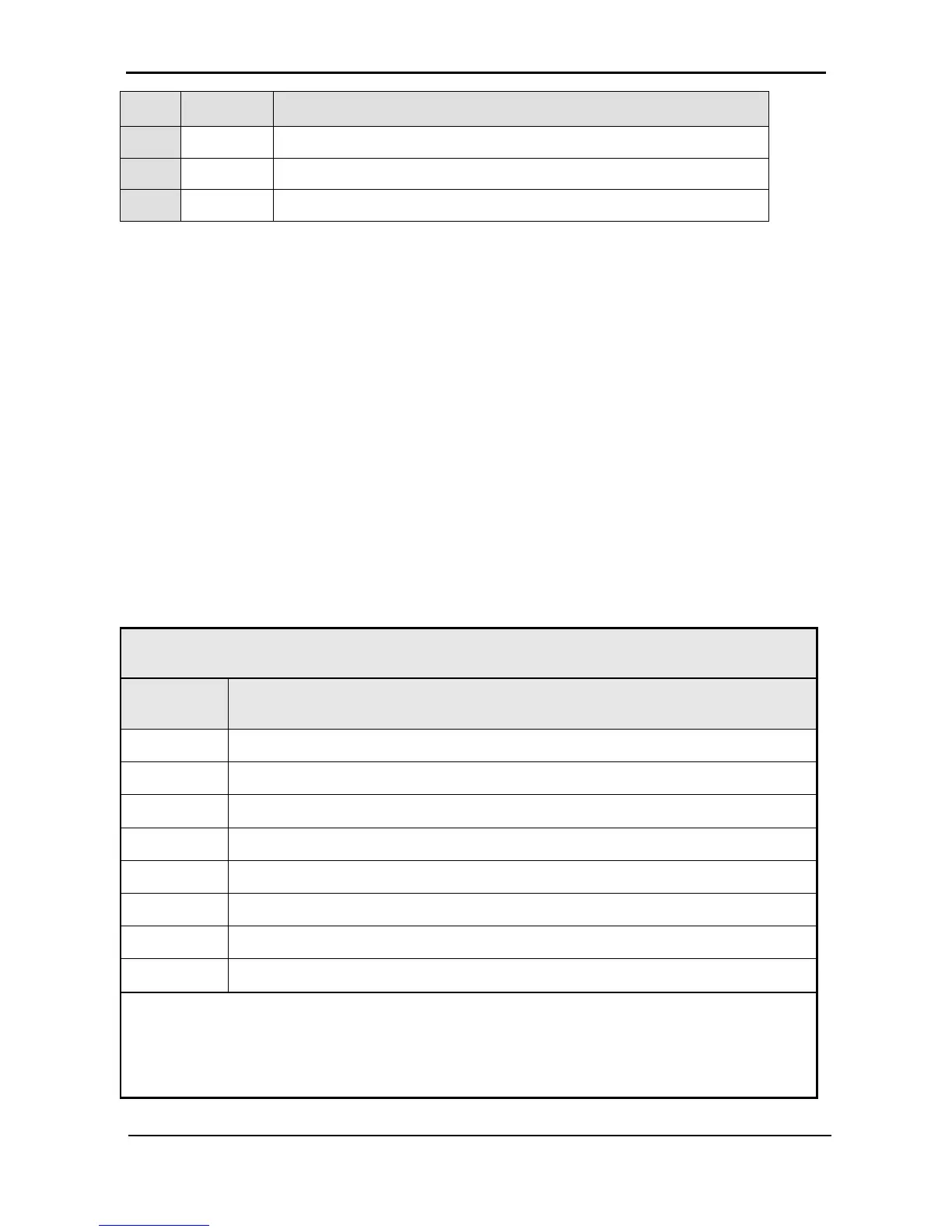
#
Message Explanation
30 UPS-CM One or more UPS’s not responding
31 STRTUP Startup time-stamp
32 ------ N.A.
Each message is formatted as follows:
Time – HH:MM:SS
Date – YY:MM:DD
Data – dc voltage between + and – terminals for all events except LOADBP and STSW status for LOADBP
events. (See below.)
Even start (IN) and end (OUT)
Description – (See Table 9 above)
Event number – 0 through 255, 255 being the most recent
Example:
11:23:56 10.01.28 865 IN -> E.P.O. 254
This message means that at 11:23:56 on January 28
th
2010, Emergency Power Off alarm was registered as
event 254; dc voltage at the time was 865 V being a sum of (V+ -N) and (V- -N).
Table 10: Interpreting the Static Switch transfer code (LOADBP)
The STSW transfer code, given as a decimal, is the sum of the eight components listed in this table.
Each component has its own weight if detected, and a weight of zero if not detected.
Inverter voltage blackout for >3 ms.
Inverter peak voltage low (brownout) (<185 V for 3x400 V, <92.5 V for 3x208 V).
Inverter peak voltage high (>400 V for 3x400 V, >200 V for 3x208 V).
Frequency beyond limits (45-65 Hz).
Inverter average voltage low (<185 V for 3x400 V, <92.5 V for 3x208 V).
Inverter average voltage high (>260 V for 3x400 V, >130 V for 3x208 V)..
Load transfer command received from the controller (not manual).
Load transfer command received from the Static Switch (manual key press).
Example: If LOADBP data = 67 = (64+2+1), this means that three conditions were present:
• (64) Instruction to transfer the load was issued by the controller.
• (2) Low peak voltage detected.
• (1) Voltage blackout encountered.