29
13. For the remaining UPSs “Unit 2” through “Unit N” (the last UPS), perform the activities described
in step 11 above, and then turn of that UPS’s circuit breakers, except that for the final unit (Unit N)
you should leave its circuit breakers ON when finished.
14. Switch ON the circuit breakers of Unit 1.
Verify that LED CR6 is lit on PC819 of Unit N and not lit on PC819 of any of the other units.
15. After 2 or 3 minutes, switch ON the battery circuit breakers of all units.
16. Verify that outputs of all units are connected to the inverter
(only green LEDs on panel of STSW unit should be lit).
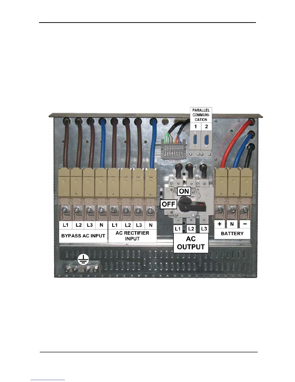
17. Switch ON the output switch of Unit 1 (vertical position).
Leave output switches of all other units in the OFF position (horizontal position). Refer to Figure 23
and Figure 24.
Figure 23: The output switch in the OFF position