4. USER INTERFACE
This section describes the buttons and indicators used to operate the POWER
+
.
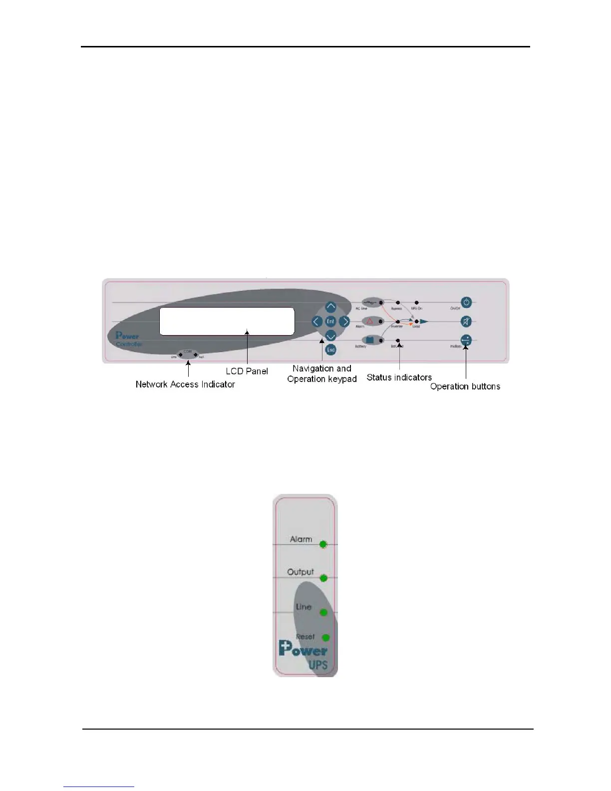
4.1 Control panel
The POWER
+
Control Panel, located on the front of the controller, provides the user with an interface to the
POWER
+
system. It includes an LCD display, a keypad, buttons and indicators for monitoring and
controlling the UPS configuration and functions. The control panel is aimed at both the end-user as well as
the service engineer. All of the POWER
+
parameters can be viewed on the control panel.
Use of the POWER
+
Control Panel is described in detail in Chapter 6 beginning on page 55.
Figure 25: Control panel
4.2 UPS module panel
The UPS module panel, located on the front of each UPS module, provides the user with the status of that
module.
Figure 26: UPS module panel