39
Figure 35: Ac power failure indication
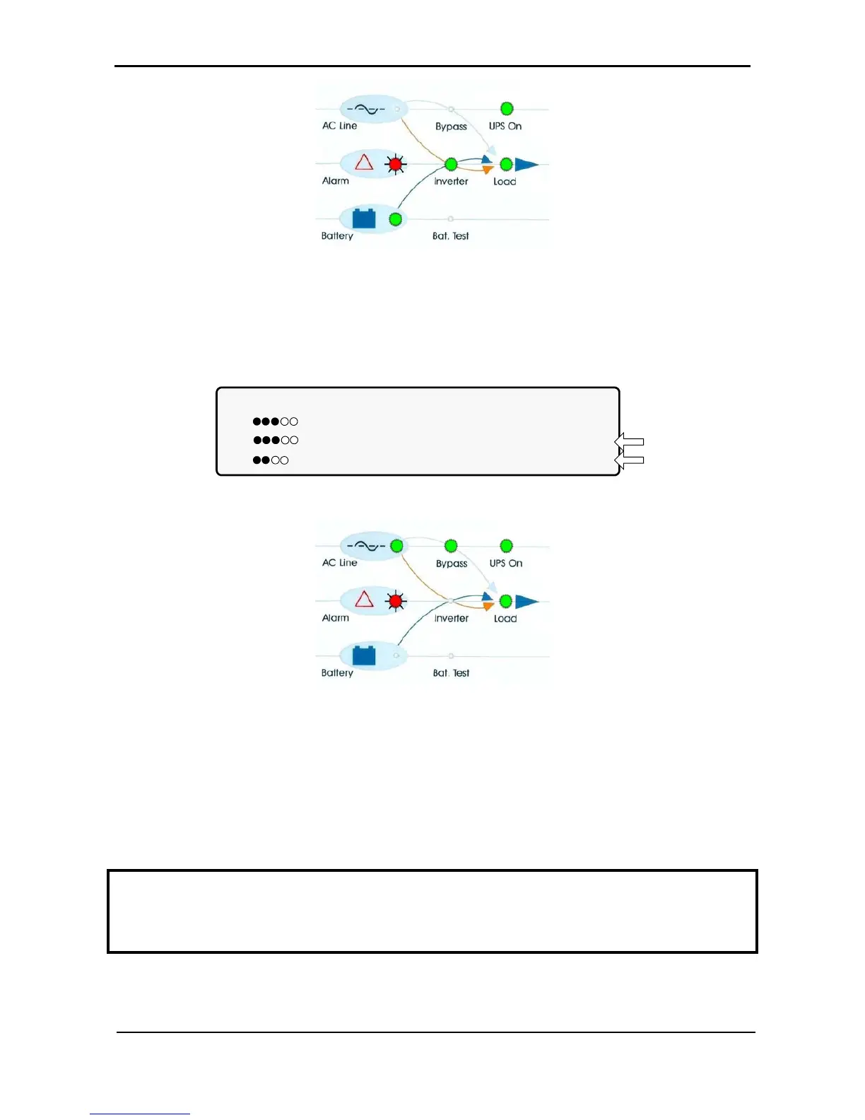
4.9.3 Bypass operation (automatic)
During Bypass operation, the ac feeds the load via the bypass static switch. The red alarm flashes to
indicate an abnormal status.
LOAD LEVEL ---12:01:11---
L1: _____ 015A, 230V BATTERY: 868V
L2: _____ 012A, 230V UPS OK (ON)
L3: ______ 011A, 230V STSW OK (BYP)
Status
indications
Figure 36: UPS in bypass mode
Figure 37: UPS in bypass mode
4.9.4 Bypass operation (manual)
If the Power+ is manually switched to bypass operation by pressing the Inv/Byp button, the load is
transferred to the mains ac input line. Transfer back to normal operation must be performed manually. The
red alarm indicator flashes to indicate an abnormal status (see Figure 37).
-
IMPORTANT OPERATIONAL NOTE:
When two (or more) Power+ units are being operated in parallel mode, and the system is manually moved
to bypass mode, the return of the system to Inverter mode must be performed on the same unit that was
used to transfer the system to bypass mode. If you attempt to return the system to Inverter mode on a unit
other than the one that was used to put the system in bypass mode, the command will not be accepted.