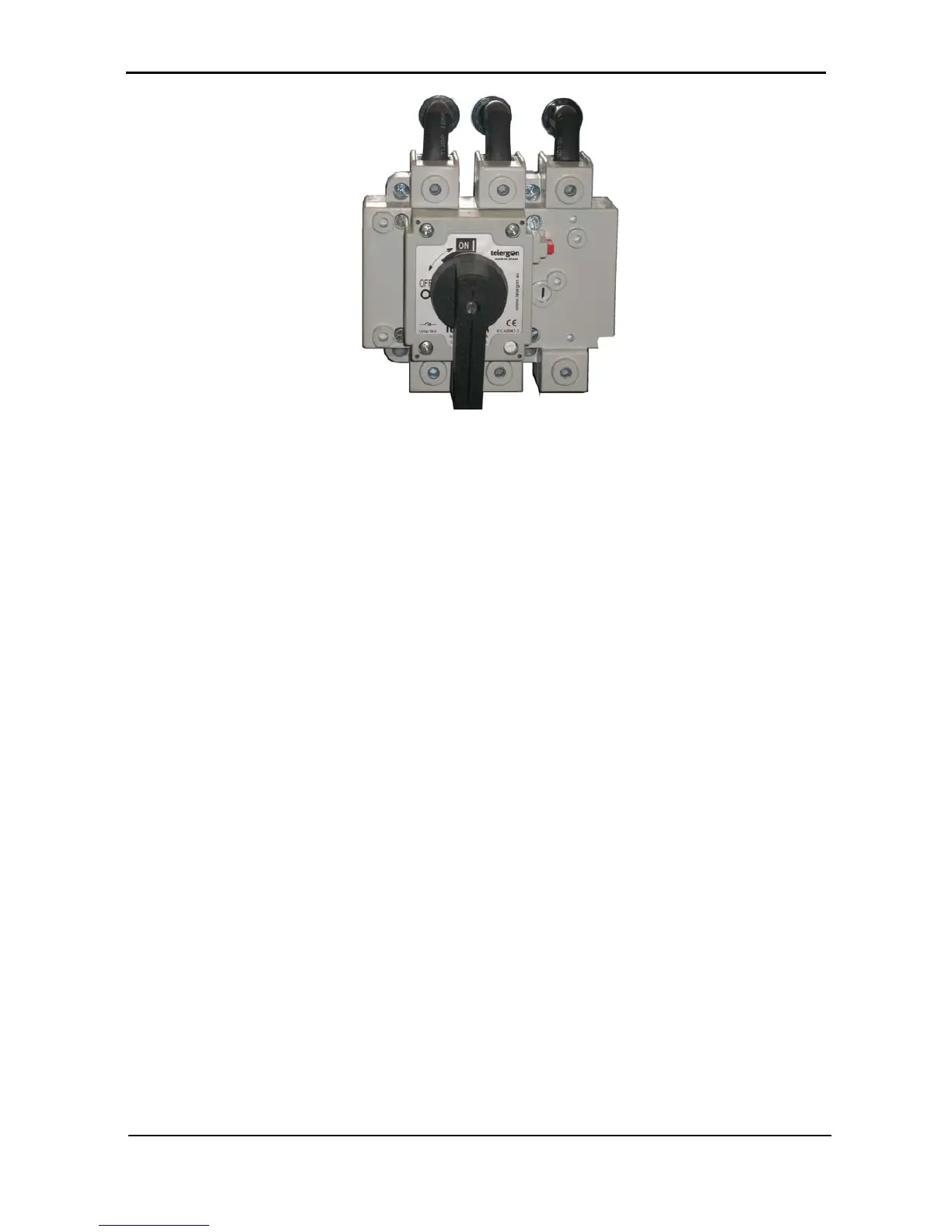
Figure 24: The output switch in the ON position
18. On Unit 1, use a voltmeter to check the ac voltage ΔV across the output circuit breaker for each
phase (R, S, and T). Do the same on Unit 2. The difference between the voltages found on Unit 1
and Unit 2 should be less than 4 V.
19. For each remaining unit, use an ac voltmeter to check the ac voltage ΔV across the output circuit
breaker for each phase (R, S, and T). Compare these voltages to the voltages found on the
previous UPS. In each case, the difference between the voltages should be less than 4V.
20. Transfer output to the bypass ac input by pressing twice on the INV/BP key on Unit 1’s control
panel.
a. Verify that the output of all units is connected to bypass (red LEDs on both STSW panels
are lit).
b. Verify that the ΔV between the identical contacts of the output switches of Unit 1 and Unit 2
(R-R’, S-S’, T-T’) is less than 4V.
c. Verify that the ΔV between the identical contacts of the output switches of Unit 1 and Unit 3
(R-R’’, S-S’’, T-T’’) is less than 4V.
d. Verify that that ΔV between the identical contacts of the output switches of Unit 1 and each
of the remaining units is less than 4V.
21. Re-transfer the output to the inverter by pressing twice on the INV/BP switch on Unit 1.
22. Transfer output to bypass ac input by pressing twice on the INV/BP key on Unit 2’s control panel.
Verify that output of all units is connected to Bypass (on each unit, the red LEDs on both STSW
panels are lit).
23. Re-transfer the output to inverter by pressing twice on the INV/BP switch on Unit 2.
24. For each remaining unit (Unit 3 through Unit N):
a. Transfer output to bypass ac input by pressing twice on the INV/BP key on that unit’s
control panel.
b. Verify that output of all units is connected to Bypass (red LEDs on both STSW panels are
lit).
c. Re-transfer the output to inverter by pressing twice on the INV/BP switch on the same unit.