x/EN ST/Na7
-
MiCOM P74
1.3.9 Control input configuration (“Ctrl I/P Config” column)
The control inputs function as software switches that can be set or reset either locally or
remotely. These inputs can be used to trigger any function that they are connected to as part
of the PSL.
This column is visible when the “Control I/P Config” setting (“Configuration” column) =
“visible”.
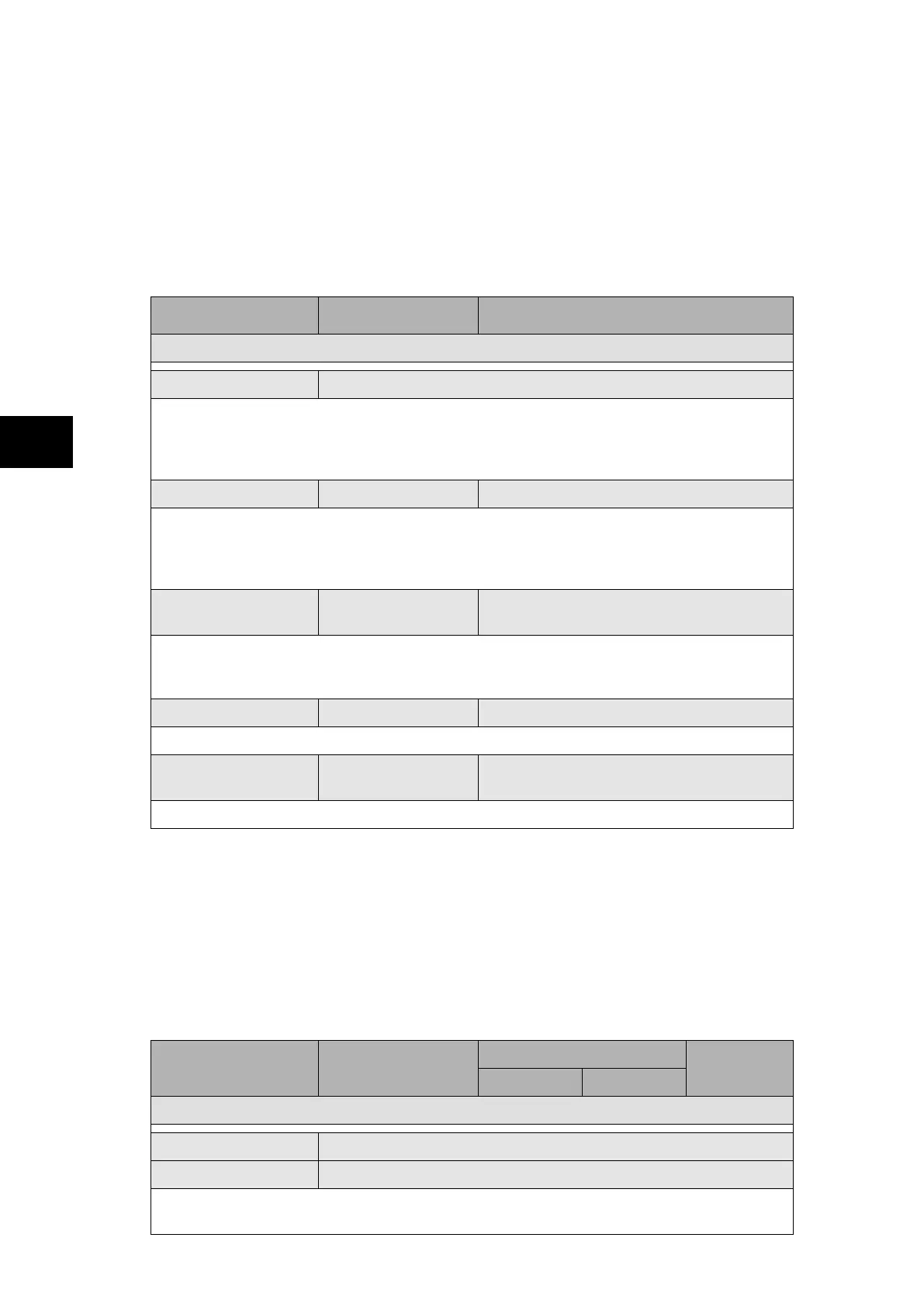
Menu Text Default Setting Available Setting
CTRL I/P CONFIG.
Hotkey Enabled 11111111111111111111111111111111
Setting to allow the control inputs to be individually assigned to the “Hotkey” menu by
setting ‘1’ in the appropriate bit in the “Hotkey Enabled” cell. The hotkey menu allows the
control inputs to be set, reset or pulsed without the need to enter the “CONTROL INPUTS”
column
Control Input 1 Latched Latched, Pulsed
Configures the control inputs as either ‘latched’ or ‘pulsed’. A latched control input will
remain in the set state until a reset command is given, either by the menu or the serial
communications. A pulsed control input, however, will remain energized for 10ms after the
set command is given and will then reset automatically (i.e. no reset command required) .
Ctrl Command 1 Set/Reset
Set/Reset, In/Out, Enabled/Disabled,
On/Off
Allows the SET / RESET text, displayed in the hotkey menu, to be changed to something
more suitable for the application of an individual control input, such as “ON / OFF”, “IN /
OUT” etc.
Control Input 2 to 32 Latched Latched, Pulsed
Configures the control inputs as either ‘latched’ or ‘pulsed’.
Ctrl Command
2 to 32
Set/Reset
Set/Reset, In/Out, Enabled/Disabled,
On/Off
Allows the SET / RESET text to be changed to “ON / OFF”, “IN / OUT” etc.
1.3.10 “InterMiCOM Comm and Conf” columns (P741 / P743)
The settings necessary for the implementation of InterMiCOM are contained within two
columns of the relay menu structure: “InterMiCOM comms” and “InterMiCOM conf”. The two
columns are visible when the “InterMiCOM” setting (“Configuration” column) = “enabled”,
with the InterMiCOM option present.
1.3.10.1 InterMiCOM communications
The “INTERMICOM COMMS” column contains all the information to configure the
communication channel and also contains the channel statistics and diagnostic facilities.
Menu Text Default Setting
Setting Range
Step Size
Min. Max.
INTERMICOM COMMS
IM Input Status 00000000
IM Output Status 00000000
The two cells display the InterMiCOM input and Output status (see P74x/EN OP section for
pin allocation)