P74x/EN MT/N
1, P742, P743
(MT) 11-
1.3.2.7 Replacement of the Coprocessor board
Before replacing a faulty Coprocessor board, disconnect fibre optic cable connections at the
rear of the relay.
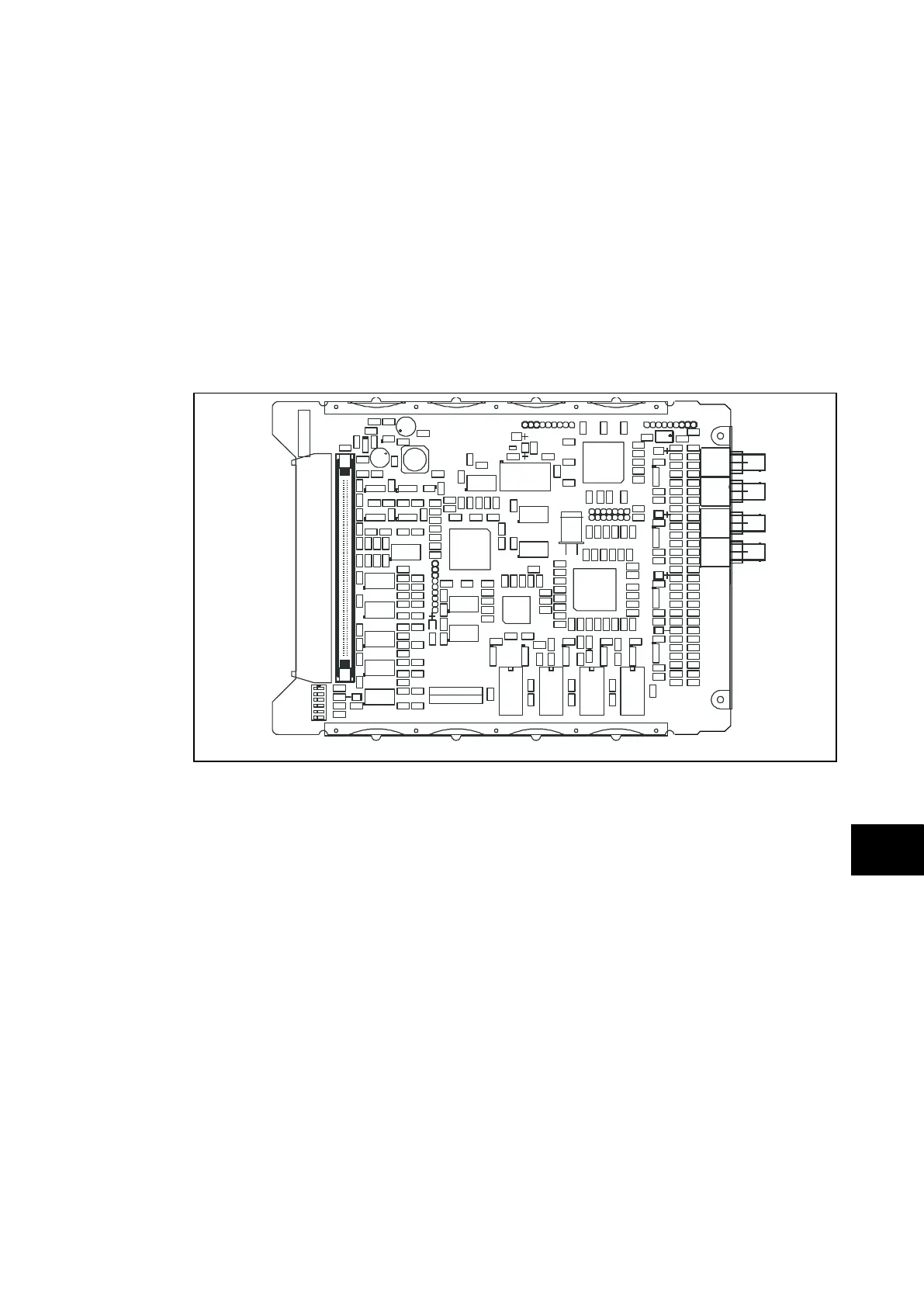
The board is secured in the case by two screws accessible from the rear of the relay, one at
the top and another at the bottom, as shown in Figure 14. Remove these screws carefully as
they are not captive in the rear panel of the relay.
Using the small metal tab on the left hand side of the input module rotate handle used for
extraction until it is in a horizontal orientation. This is necessary so that the two PCB
connectors on the underside of the Coprocessor board PCB do not catch the handle as the
PCB is extracted.
Gently pull the faulty Coprocessor board PCB forward and out of the case.
FIGURE 14: TYPICAL COPROCESSOR BOARD
To help identify that the correct board has been replace, Figure 18 illustrates the layout of
the Coprocessor board with dual fibre optic communications channels fitted. The
Coprocessor board boards with a single communications channel (used in relays for two
ended feeders where dual redundant communications channels are not required) use the
same PCB layout but have fewer components fitted.
The replacement PCB should be carefully slid into the appropriate slot, ensuring that it is
pushed fully back and the board securing screws are re-fitted.
Refit the fibre optic cable connections, ensuring that they are in the correct locations.
Refit the front panel using the reverse procedure to that given before. After refitting and
closing the access covers on size 60TE/80TE cases, press at the location of the
hinge-assistance T-pieces so that they click back into the front panel moulding.
Once the relay has been reassembled after repair, it should be recommissioned in
accordance with the instructions in sections 1 to 8 inclusive of the commissioning and
maintenance section P74x/EN CM.