Na7
-
MiCOM P741, P742
1.2.8.3 Voltage criteria for busbar Protection
Where there is a need to use voltage criteria such as undervoltage, zero sequence
overvoltage, direct overvoltage or inverse undervoltage, an external device such as a P923
must be connected to the VT(s).
1.2.8.3.1 VT(s) connected to the Bar(s) and the Central Unit,
This device calculates the required voltage information and sends the release information to
the Central Unit via an output contact to opto input communication link. The required logic is
made in the P741 PSL.
The 87BB trip order can be blocked in the CU using 2 logic input sets, one to block the
phase element, the second to block the SEF element and that per zone:
• INP Block 3Ph Z1 to Z8
• INP Block SEF Z1 to Z8
If 2 bus section are included in the same zone (isolator bus section or during double
switching), an OR gate between the 2 voltage criteria from the different bus sections is used
to confirm the fault detection.
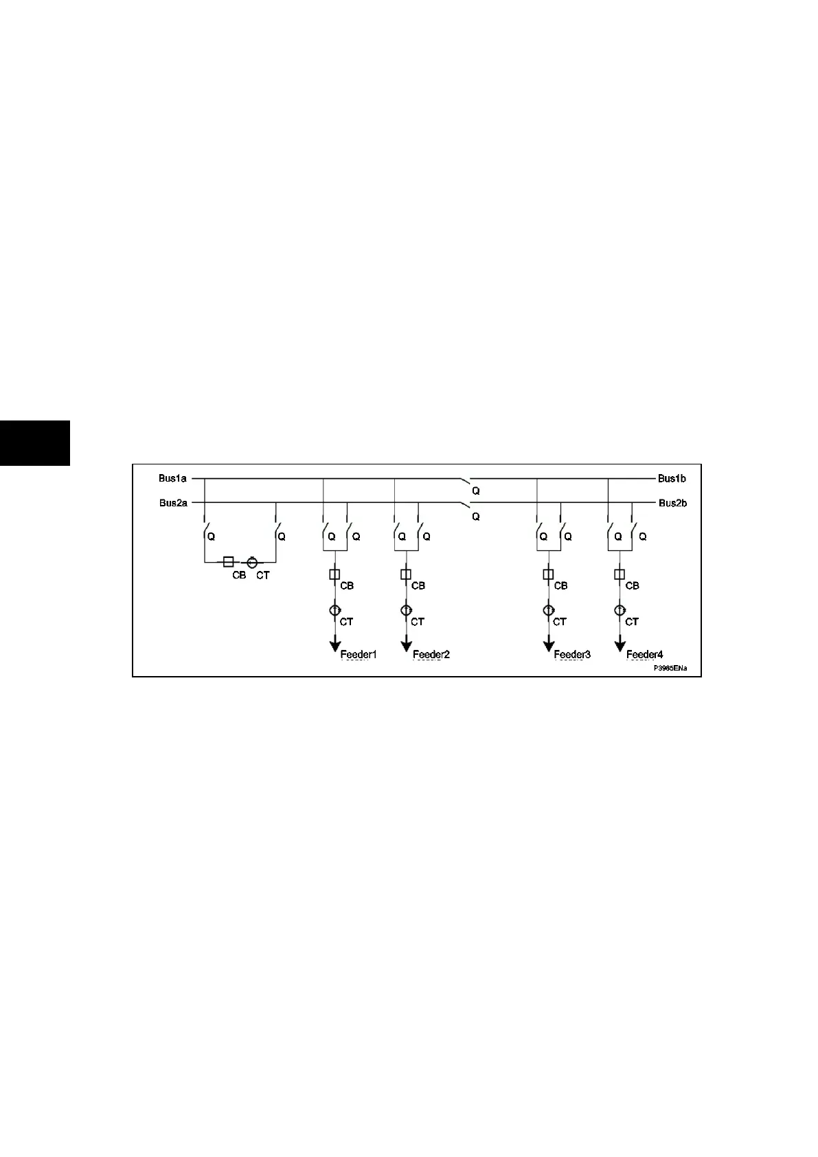
Example:
FIGURE 5: VT(s) CONNECTED TO THE BAR(s) AND THE CENTRAL UNIT
• When the isolator bus sections are open:
o The faults in zone 1a are confirmed by the VT connected to the bus section 1a
o The faults in zone 1b are confirmed by the VT connected to the bus section 1b
• When the isolator bus sections are closed:
o The section 1a and 1b are in the same zone, the faults are confirmed by the VT
connected to the bus section 1a OR the VT connected to the bus section 1b
• When the isolator bus sections are open and during double switching, when both
isolators of a feeder are closed:
o The faults in zone 1a / 2a are confirmed by the OR between VT connected to bus 1a
and 2a
1.2.8.3.2 VT(s) connected to the Line(s) and a Peripheral Unit,
This device calculates the required voltage information and sends the release information to
a Peripheral Unit via an output contact to opto input communication link. The required logic is
made in the P742 or P743 PSL.