CM
6.2.2 RB
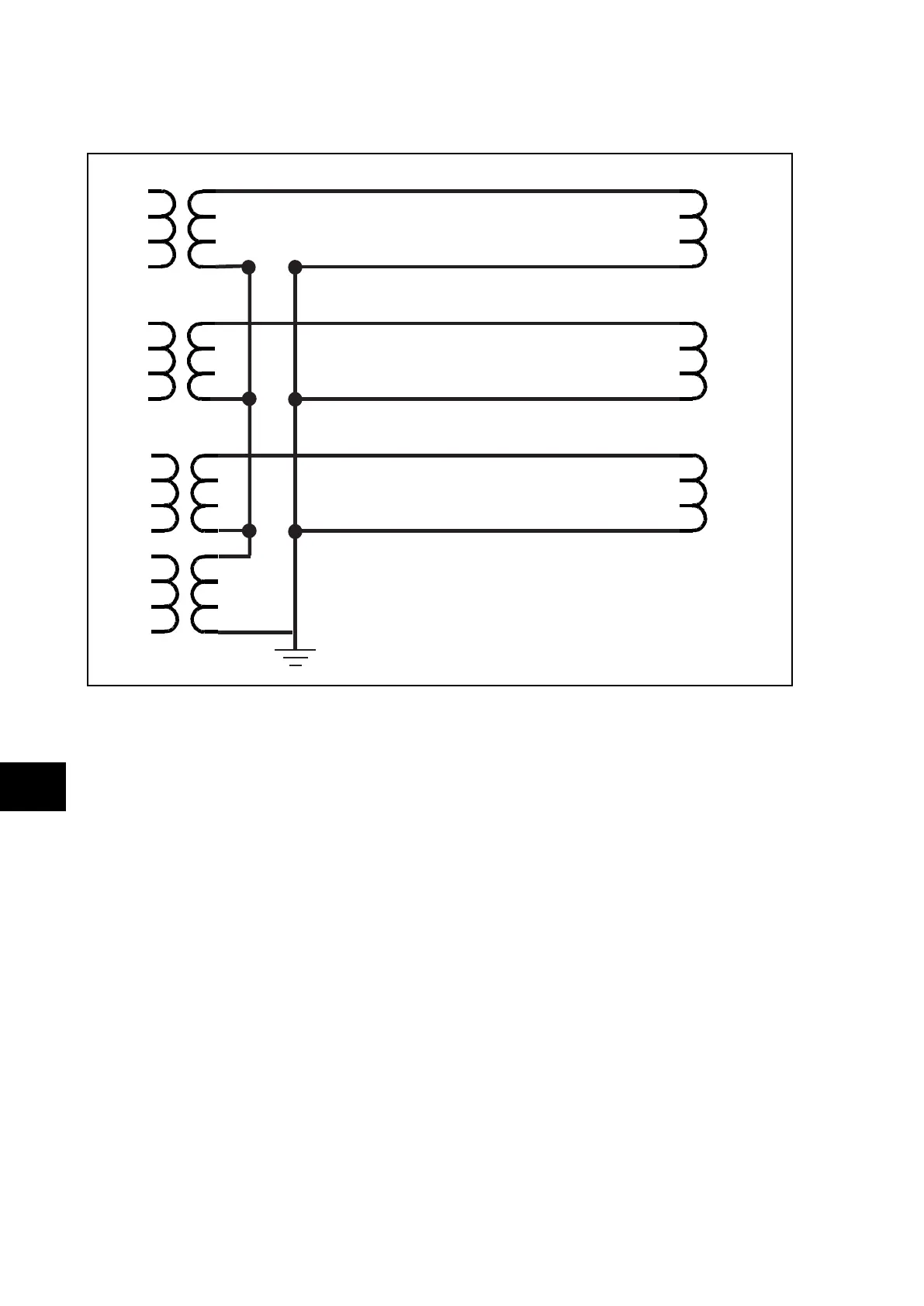
Ph
/ RB
N
is close to 3
P3901ENa
CT
A
CT
B
CT
C
PU
I
A
I
B
I
C
I
N
RB
A
= RAN / 2
RB
B
= RBN / 2
RB
C
= RCN / 2
RB
N
= (RB
A
+ RB
B
+ RB
C
) / 9
The highest of the 3 phase values must be multiplied by 1.25 (25% increase at a 75°C
temperature) and set in cell [CT/TT Ratios, RB in ohms].
The average of the 3 phase values (RB
A
, RB
B
, RB
C
) should be divided by the neutral
resistance, RB
N
, and set in cell [CT/TT Ratios, RB
Ph
/ RB
N
].
Note: The use of the Excel spreadsheet tool called “LeadBurdenR” is
strongly recommended to calculate these values.
6.3 Demonstrate Correct Relay Operation
The purpose of these tests is as follows:
− To determine that the primary protection function of the relay, current differential, can
trip according to the correct application settings.
− To verify correct setting of any backup phase overcurrent protection.
− To verify correct assignment of the inputs, relays and trip contacts, by monitoring the
response to a selection of fault injections.
6.3.1 Current Differential Bias Characteristic
To avoid spurious operation of any Overcurrent, earth fault or breaker fail elements, these
should be disabled for the duration of the differential element tests. This is done in the relay’s
CONFIGURATION column. Ensure that cells, [Overcurrent Prot], [Earth Fault Prot] and [CB