P74x/EN PL/N
1, P742, P743
(PL) 7-
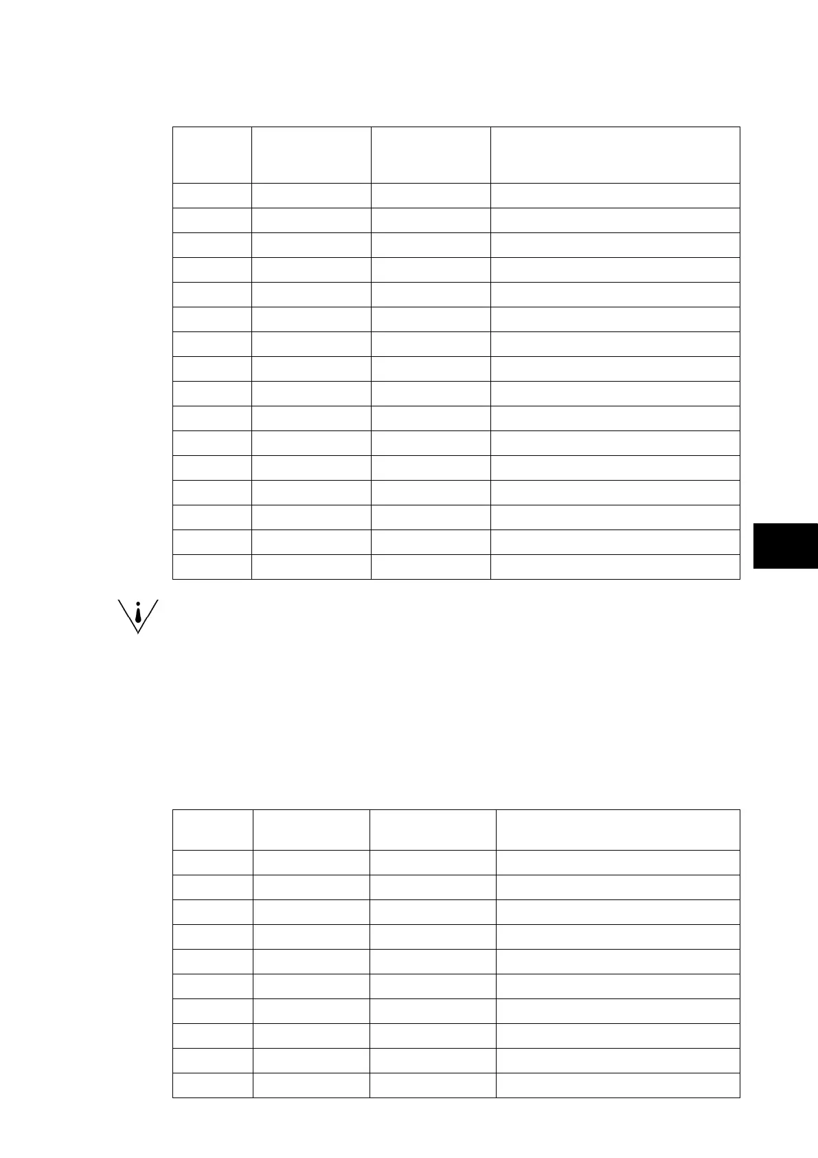
Peripheral Unit P743:
Relay
Contact
Number
P74x Relay Text
P74x Relay
Conditioner
Function
1 Relay Label 01 Pick-up 0/0 Trip 87BB or 50BF backtrip (fixed)
2 Relay Label 02 Pick-up 0/0 Trip 87BB or 50BF backtrip (fixed)
3 Relay Label 03 Pick-up 0/0 Trip 87BB or 50BF backtrip (fixed)
4 Relay Label 04 Pick-up 0/0 Circuit Breaker failure
5 Relay Label 05 Pick-up 0/0 Circuit Breaker failure or out of service
6 Relay Label 06 Pick-up 0/0 Circuit Breaker failure retrip
7 Relay Label 07 Pick-up 0/0 Trip or Dead Zone Fault
8 Relay Label 08 Pick-up 0/0 Circuit Breaker or Isolator status alarm
9 Relay Label 09 Pick-up 0/0 Circuit Breaker failure retrip phase A
10 Relay Label 10 Pick-up 0/0 Circuit Breaker failure retrip phase B
11 Relay Label 11 Pick-up 0/0 Circuit Breaker failure retrip phase C
12 Relay Label 12 Pick-up 0/0 Not Mapped
13 Relay Label 13 Pick-up 0/0 Not Mapped
14 Relay Label 14 Pick-up 0/0 Not Mapped
15 Relay Label 15 Pick-up 0/0 Not Mapped
16 Relay Label 16 Pick-up 0/0 Not Mapped
Note: It is essential that Relay 1, 2 and 3 are used for tripping purposes as
this output is directly driven in the fixed logic to obtain the typical 13ms
tripping time.
A fault record can be generated by connecting one or a number of contacts to the “Fault
Record Trigger” in PSL. It is recommended that the triggering contact be ‘self reset’ and not
a latching. If a latching contact were chosen the fault record would not be generated until the
contact had fully reset.
1.13 Function key input mapping
The default mappings for each of the function key inputs are as shown in the following table:
Central Unit P741:
LED
Number
Text Setting Function
1 FnKey 1 Normal To reset Zone or CZ circuitry fault
2 FnKey 2 Normal To reset Zone or CZ PU error fault
3 FnKey 3 Normal To Disable All protections (CU & PU)
4 FnKey 4 Toggled To block in Zone 1: 87BB & 50BF
5 FnKey 5 Toggled To block in Zone 2: 87BB & 50BF
6 FnKey 6 Normal To reset CU Indications
7 FnKey 7 Normal To reset CU & PU Indications
8 FnKey 8 Normal To reset PU Trip Latch
9 FnKey 9 Normal To trigger the Manual DR
10 FnKey 10 Not Used Not used