pplication Notes
P74x/EN AP/N
1, P742, P743 (AP) 6-
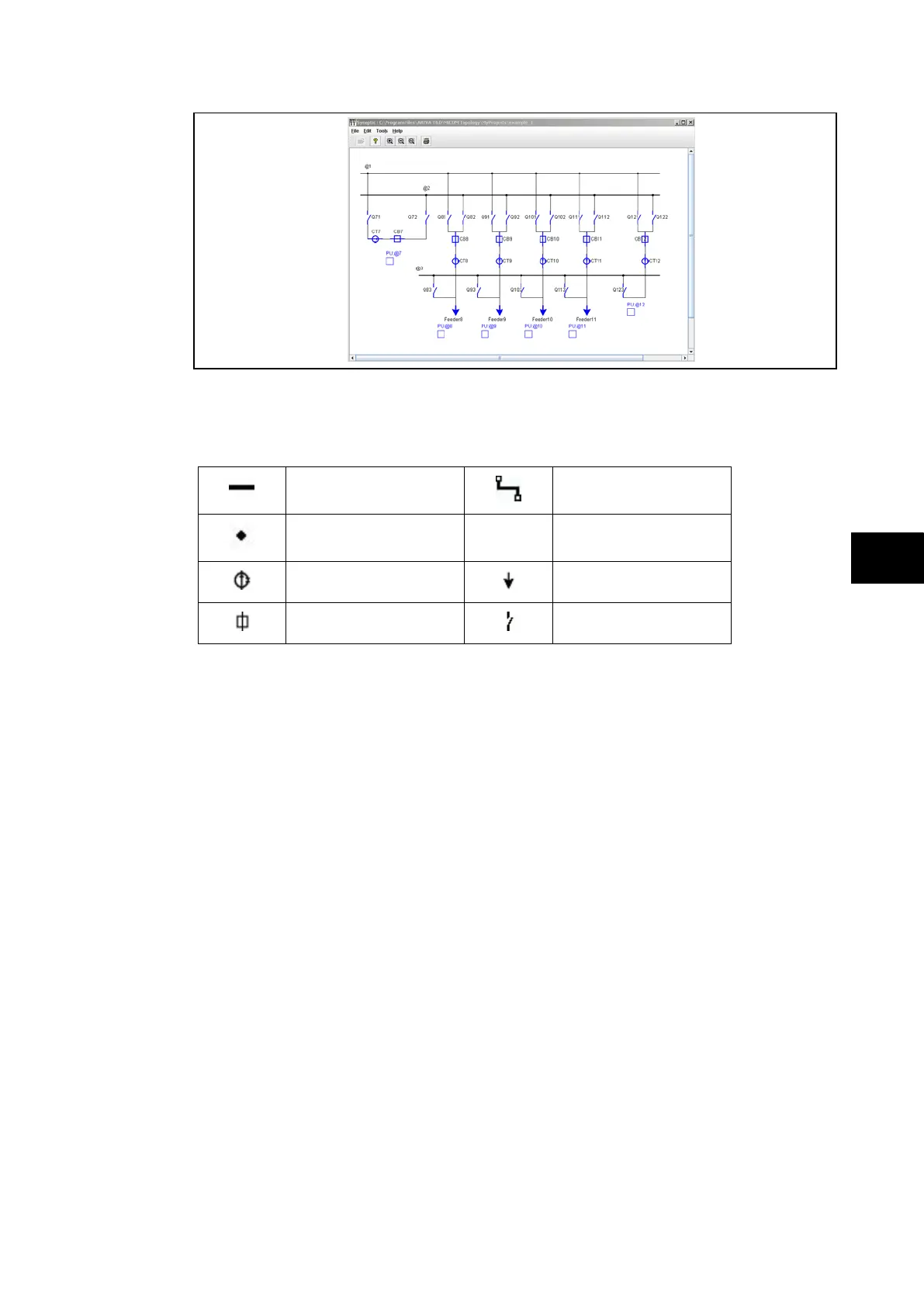
FIGURE 11: P74x SYNOPTIC
The topology configuration tool uses standard symbols for creating the system model by
simply dragging and dropping in the configuration screen.
Bar
Link
Node
Current Transformer
Feeder
Circuit Breaker (CB)
Isolator
FIGURE 12: TOPOLOGY CONFIGURATOR OBJECTS
The switchgear/busbars are then labelled and assigned to relevant peripheral units.
When the topology has been fully defined it is compiled and then downloaded to each PU
and the CU.
6.2 Nodal Assignment
Four files are created from the topological model. The first identifies each piece of primary
plant such as circuit breakers, isolators, current transformer (CT), bus section and feeders.
The second file identifies the connections between each piece of primary plant and the third
calculates the topological nodal assignment thus making it possible to link to each peripheral
unit with associated primary plant of the system. The fourth file will be used by the Dynamic
Synoptic software to visualise in real time the substation.
Algorithms search to determine the electrical topology. These operate in real time in the
P74x scheme. They start with the information obtained regarding the state of the primary
plant. A state table is created and associated with each device. According to the algorithm,
this state table gathers the data related to the physical states of the primary plant taken by
the unit.
The results of these algorithms are then subjects of a further algorithm, developed from
operational research. This algorithm identifies commonality between nodes and merges
nodes where appropriate. The new node includes all common nodes.
The principal characteristics of this algorithm mean that the scheme has the following
benefits:
• Adaptability to various substation configurations
• Permanent identification of current nodes
• Permanent identification of physical links for each zone
• Reference to the neighbouring circuit breakers for each point of the circuit