-
• a 16-character by 3-line alphanumeric liquid crystal display (LCD).
• a 9-key keypad comprising 4 arrow keys
( , , and ), an enter key (), a
clear key (
), a read key () and 2 hot keys ().
• 12 LEDs; 4 fixed function LEDs on the left-hand side of the front panel and 8
programmable function LEDs on the right-hand side.
Under the top hinged cover:
• the relay serial number, and the relay’s current and voltage rating information*.
Under the bottom hinged cover:
• battery compartment to hold the
1
/
2
AA size battery which is used for memory
back-up for the real time clock, event, fault and disturbance records.
• a 9-pin female D-type front port for communication with a PC locally to the relay (up to
15m distance) via an RS232 serial data connection.
• a 25-pin female D-type port providing internal signal monitoring and high speed local
downloading of software and language text via a parallel data connection.
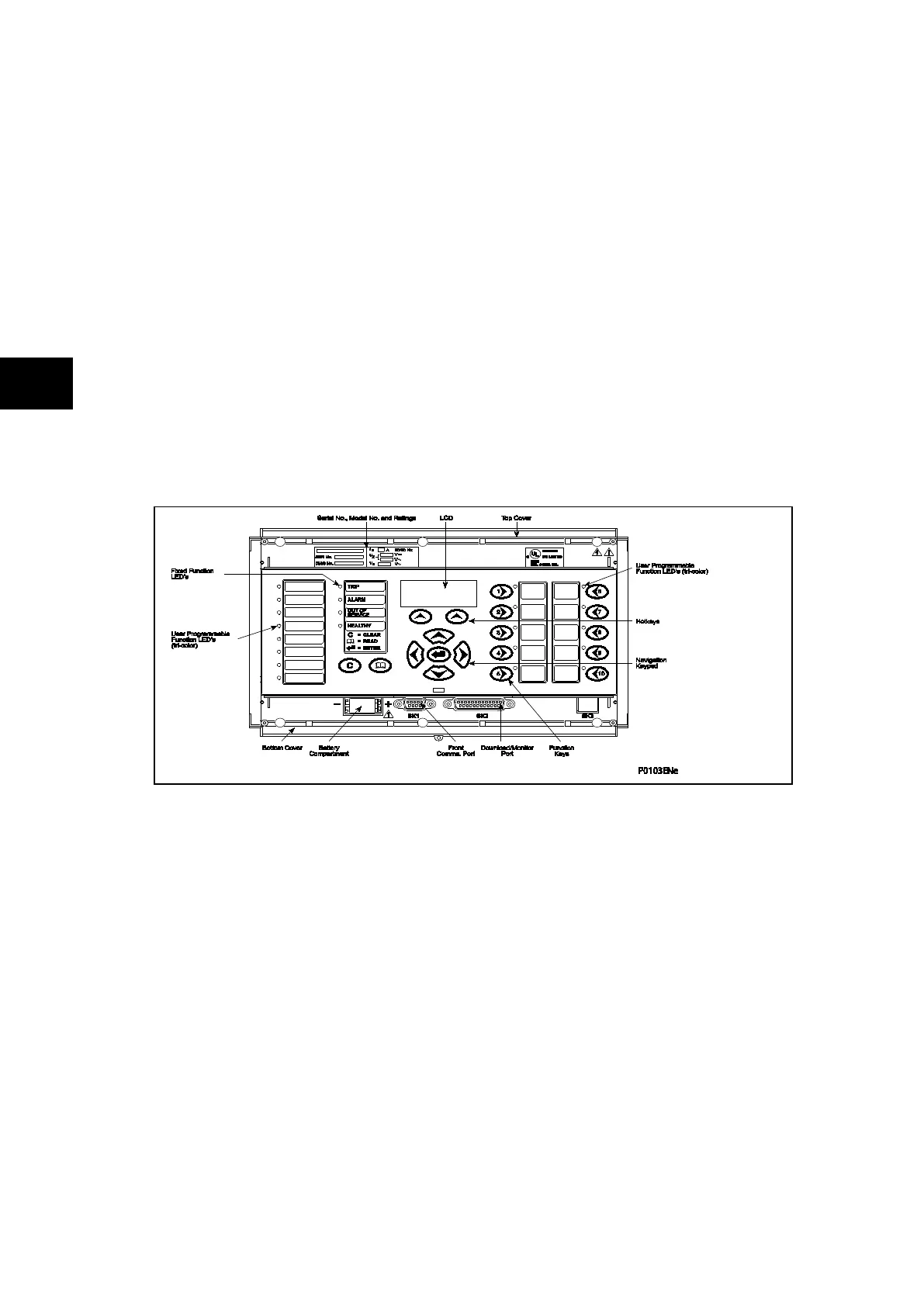
FIGURE 2: RELAY FRONT VIEW (EXAMPLE FOR P743 – 60 TE)
The front panel of the relay includes the following, as indicated in Figure 2:
− a 16-character by 3-line alphanumeric liquid crystal display (LCD)
− a 19-key keypad comprising 4 arrow keys (, , and ), an enter key
(), a clear key (), a read key (), 2 hot keys () and 10 ( − )
programmable function keys
− Function key functionality:
− The relay front panel features control pushbutton switches with programmable
LEDs that facilitate local control. Factory default settings associate specific relay
functions with these 10 direct-action pushbuttons and LEDs e.g. reset
indications. Using programmable scheme logic, the user can readily change the
default direct-action pushbutton functions and LED indications to fit specific
control and operational needs.
− Hotkey functionality: When the functionality is disabled:
− SCROLL
Starts scrolling through the various default displays.
− STOP
Stops scrolling the default display.