x/EN PL/Na7
7-
MiCOM P74
1.15 Fault recorder start mapping
The default mapping for the signal which initiates a fault record is as shown in the following
table:
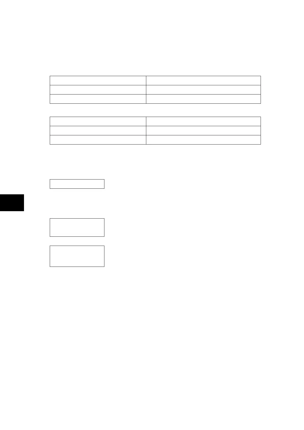
Central Unit (P741):
Initiating Signal Fault Trigger
Trip 87BB Initiate fault recording from main protection trip
Trip 50BF Initiate fault recording from main protection trip
Peripheral Unit (P742 and P743):
Initiating Signal Fault Trigger
Any Trip Initiate fault recording from main protection trip
Dead zone fault Initiate fault recording from main protection trip
1.16 PSL DATA column
The P74x relay contains a PSL DATA column that can be used to track PSL modifications. A
total of 12 cells are contained in the PSL DATA column, 3 for each setting group. The
function for each cell is shown below:
Grp. PSL Ref. When downloading a PSL to the relay, the user will be
prompted to enter which group the PSL is for and a reference
identifier. The first 32 characters of the reference ID will be
displayed in this cell. The and keys can be used to
scroll through 32 characters as only 16 can be displayed at any
one time.
18 Nov 2002
08:59:32.047
This cell displays the date and time when the PSL was down
loaded to the relay.
Grp. 1 PSL
ID - 2062813232
This is a unique number for the PSL that has been entered.
Any change in the PSL will result in a different number being
displayed.
Note: The above cells are repeated for each setting group.