CM
6.2 How to measure the Burden Resistance (R
B
)
P3747ENc
V
A
A
B
C
N
CT
A
CT
B
CT
C
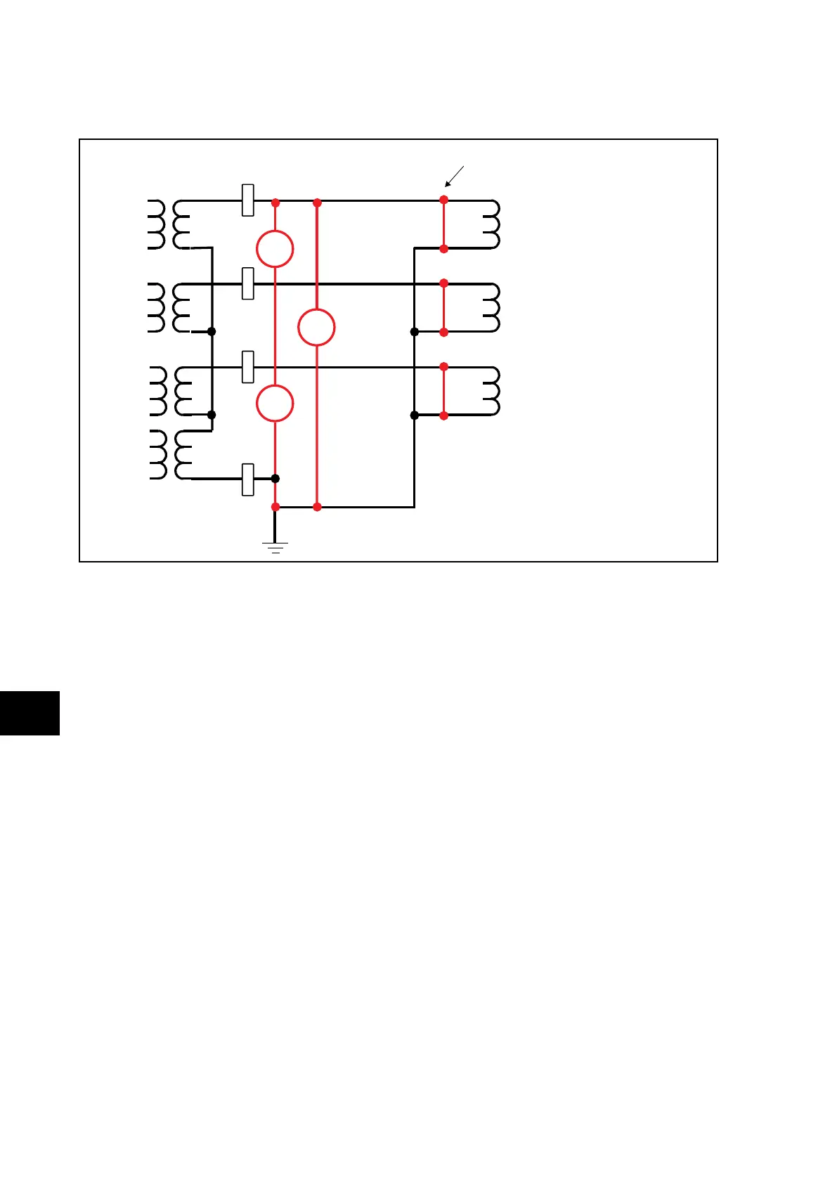
Short-circuit of the secondary
winding of the current transformer
(HV sit e)
P992 or MMLG
PU
I
A
I
B
I
C
I
N
Insertion of the test block to open current circuit
=
FIGURE 6: WIRING
1. Short-circuit the secondary winding of the HV current transformer (see above)
2. Open the wiring by inserting a test block
3. Connect the current testing circuit of the test block (phase + neutral).
4. Inject a current (1A recommended) and measure the voltage at the resistive circuit
terminals.
5. An Excel tool is available in order to help calculate the values below accurately.
6. Calculate the load resistance R
B
per phase using the following equation:
R
B
= U
measured
/ I
injected
Repeat the above operation for each resistive circuit:
RAN between loads A and N
RBN between loads B and N
RCN between loads C and N
RAB between loads A et B