x/EN MR/Na7
Measurements and Recording
-
MiCOM P74
3. DISTURBANCE RECORDER
The integral disturbance recorder has an area of memory specifically set aside for record
storage. The number of records that may be stored by the relay is dependent upon the
selected recording duration. The relay can typically store a minimum of 50 records, each of
1.2 seconds duration in the CU and up to 10.5 seconds in a PU. Disturbance records
continue to be recorded until the available memory is exhausted, at which time the oldest
record(s) are overwritten to make space for the newest one.
The recorder stores actual samples that are taken at a rate of 12 samples per cycle in the
Central Unit (CU) and in the Peripheral Units (PU).
Minimum delay between 2 disturbance records (in the CU) is 5s.
Each disturbance record consists of 8 analogue data channels in the CU and 4 analogue
data channels in the Pus and 32 digital data channels. The relevant CT ratios for the
analogue channels are also extracted to enable scaling to primary quantities.
The "DISTURB RECORDER" menu columns are presented in the “Settings” section
P74x/EN ST. The following tables give default setting configuration for central and peripheral
units.
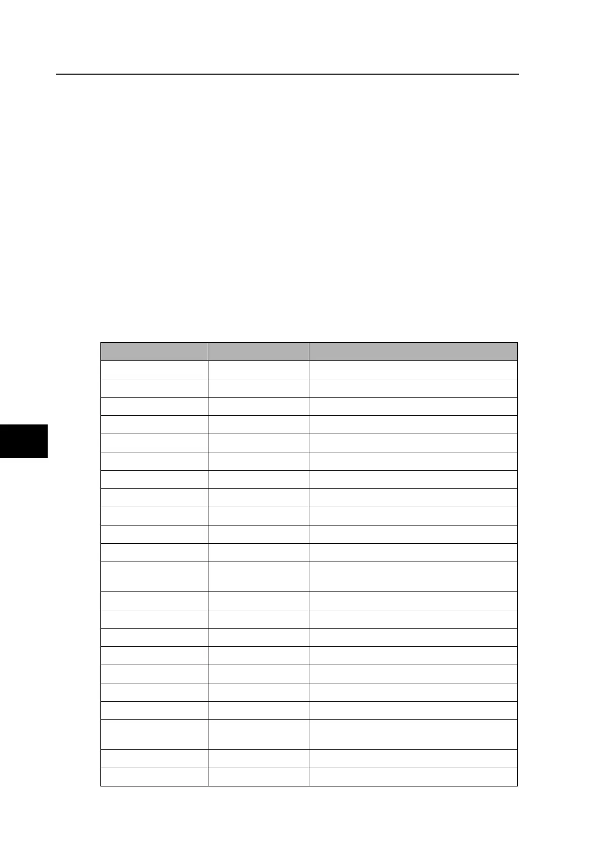
3.1 “Disturb recorder” column – Central Unit P741
Menu Text Default Setting Explanation
Analog Channel 1 I
A
diff Phase A differential calculated current
Analog. Channel 2 I
B
diff Phase B differential calculated current
Analog. Channel 3 I
C
diff Phase C differential calculated current
Analog. Channel 4 I
N
diff Neutral differential calculated current
Analog. Channel 5 I
A
bias Phase A bias calculated current
Analog. Channel 6 I
B
bias Phase B bias calculated current
Analog. Channel 7 I
C
bias Phase C bias calculated current
Analog. Channel 8 I
N
bias Neutral bias calculated current
Digital Input 2 Circt Flt Lck z1 Circuitry fault blocks zone 1 digital channel
Digital Input 2 Circt Flt Lck z2 Circuitry fault blocks zone 2 digital channel
Digital Input 3 87BB Blocked digital 87BB Blocked channel
Digital Input 4 Ext Start DR
External start of the disturbance recorder
digital channel
Digital input 5 Earth Fault Earth fault digital channel
Digital input 6 Fault Check zone Fault Check zone digital channel
Digital input 7 Fault phase A Fault phase A digital channel
Digital input 8 Fault phase B Fault phase B digital channel
Digital input 9 Fault phase C Fault phase C digital channel
Digital input 10 Flt 87BB zone 1 Fault 87BB zone 1 digital channel
Digital input 11 Flt 87BB zone 2 Fault 87BB zone 2 digital channel
Digital input 12 Manual Start DR
Manual start of the disturbance recorder
digital channel
Digital input 13 Topo/Set Changed Topology or setting changed digital channel
Digital input 14 Trip Manual zone Manual trip of the zone digital channel