pplication Notes
P74x/EN AP/N
1, P742, P743 (AP) 6-
The above example shows a double busbar with a bus coupler. It is split into two zones.
There are n feeders connected to the busbar. The bus coupler circuit breaker can have
either a single CT (solution 1) on one side or CTs on both sides (solution 2).
This configuration requires 1 central unit and n + 1 peripheral units for solution 1 or n + 2
peripheral units for solution 2. (The additional peripheral units being for the bus coupler
CTs). The type of peripheral unit used for each bay will depend on the i/o requirements of
the bay in question.
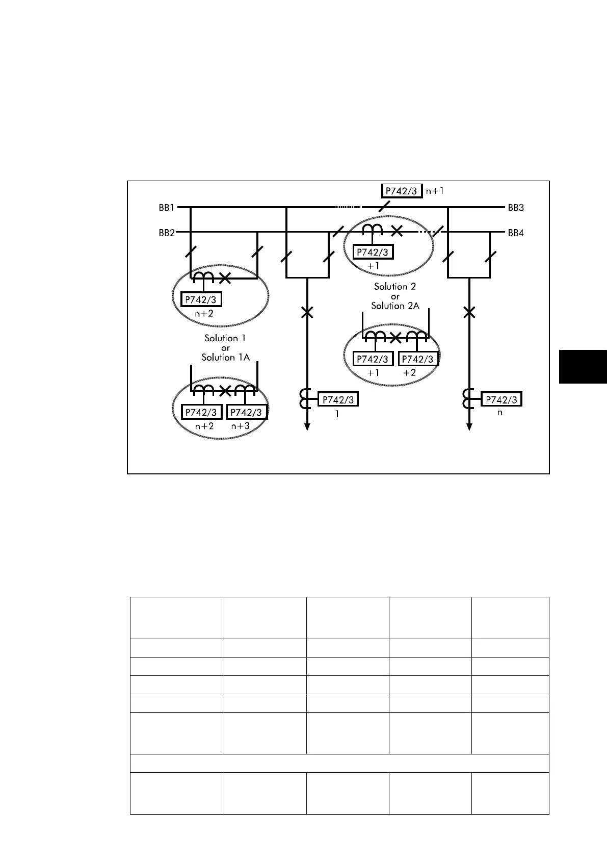
FIGURE 33: TRADITIONAL DOUBLE BUSBAR APPLICATION
WITH BUS COUPLER AND BUS SECTION
The above example shows a double busbar with both a bus section and a bus coupler. It is
split into four zones. There are n feeders connected to the busbar. The bus coupler and bus
section circuit breakers can have either a single CT (solution 1 and 2) on one side or CTs on
both sides (solution 1a or 2a). This configuration requires 1 central unit and n plus the
following number of peripheral units. The total number of peripheral units required allows for
a peripheral unit for the bus section isolator on the upper bar.
Solution Solution A
& 1 CT on BS
Solution B
& 2 CT on BS
Solution C
& 2 CT on BS
Solution D
& 1 CT on BS
Solution 1
Solution 1a
Solution 2
Solution 2a
Number of
peripheral units
required
n + 2 n + 4 n + 3 n + 3
If a second bus coupler is added i.e. one bus coupler either side of the bus section
Using solution 1
for the 2
nd
coupler