x/EN PL/Na7
7-
MiCOM P74
Peripheral Unit P743:
LED
Number
Text Setting Function
1 FnKey 1 Normal To reset the Latches
2 FnKey 2 Normal To reset the Trip Latch
3 FnKey 3 Not Used Not used
4 FnKey 4 Toggled To select the 50BF Disable mode
5 FnKey 5 Toggled To select the Overhaul mode
6 FnKey 6 Not Used Not used
7 FnKey 7 Not Used Not used
8 FnKey 8 Not Used Not used
9 FnKey 9 Not Used Not used
10 FnKey 10 Not Used Not used
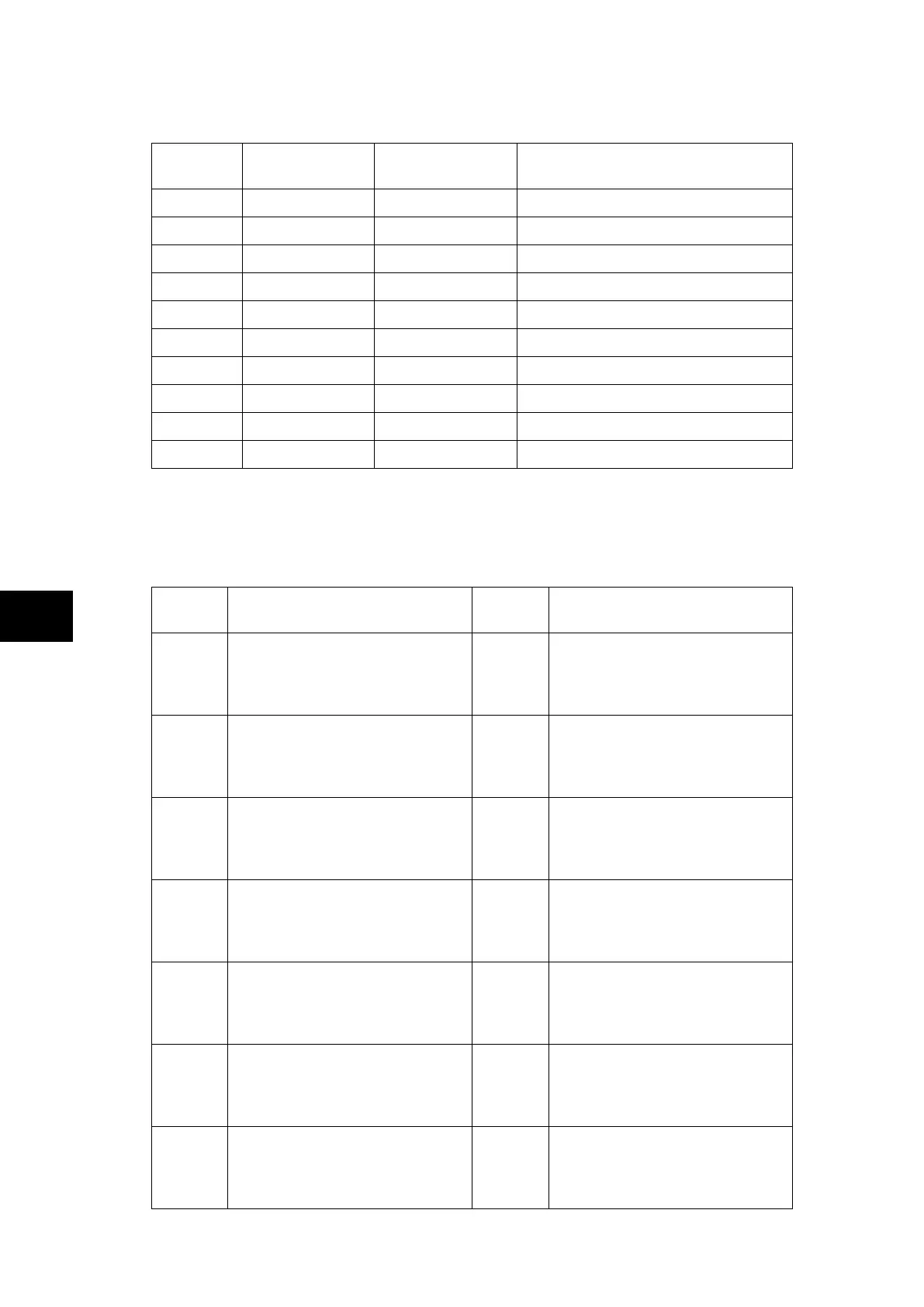
1.14 Programmable LED output mapping
The default mappings for each of the programmable LEDs are as shown in the following
table:
Central Unit P741:
LED
Number
LED Input Connection/Text Latched P74x LED Function Indication
1
LED1 Red
LED1 Yellow
LED1 Green
Yes
87BB fault on phase A
Not used
Not used
2
LED2 Red
LED2 Yellow
LED2 Green
Yes
87BB fault on phase B
Not used
Not used
3
LED3 Red
LED3 Yellow
LED3 Green
Yes
87BB fault on phase C
Not used
Not used
4
LED4 Red
LED4 Yellow
LED4 Green
Yes
50BF Trip Zone 1
87BB & 50BF Trip Zone 1
87BB Trip Zone 1
5
LED5 Red
LED5 Yellow
LED5 Green
Yes
50BF Trip Zone 2
87BB & 50BF Trip Zone 2
87BB Trip Zone 2
6
LED6 Red
LED6 Yellow
LED6 Green
No
Zone 1 blocked by itself
Zone 1 blocked by Check Zone
Zone 1 protected
7
LED7 Red
LED7 Yellow
LED7 Green
No
Zone 2 blocked by itself
Zone 2 blocked by Check Zone
Zone 2 protected