CM
CB unavailable:
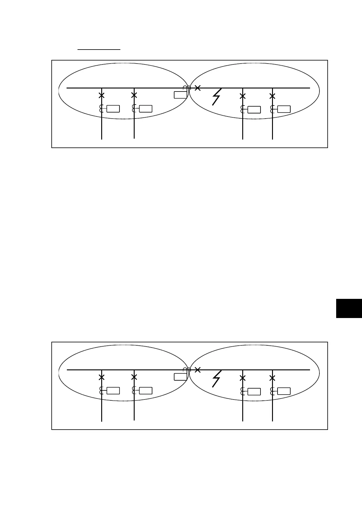
P3753ENa
PU4 PU5
PU3
PU1
PU2
Zone 1 Zone 2
FIGURE 11: CB UNAVAILABLE
Apply an internal fault in zone 2 and energise the opto input of PU3 “CB unavailable” and
check that both bus-section 1 tripped simultaneously.
Note: If the input “CB unavailable” is energised, the CB will be not tripped
and is normally used only for bus-coupler.
IMPORTANT: THE TIME INDICATED ON THE CU LCD IS THE DURATION OF THE
OPERATION OF THE CU TRIP ORDER + 250MS (TIME OF THE PU TO
CU MINIMUM DURATION SIGNAL INFORMATION).
The time indicated on a PU LCD is the duration of the operation of this PU backtrip
command with 200ms drop off.
The backtrip order is equal to (the maximum between the fault clearance time and 250 ms) –
tBF4 pick-up time.
For example, if tBF4 = 200ms and the fault is cleared before 450ms, the CU displayed
value will be 450ms and the PU displayed value will be 650ms.
For example, if tBF4 = 200ms and the fault is cleared in 500ms, the CU displayed value will
be 500ms and the PU displayed value will be 700ms.
6.3.3.3
Internal initiation Breaker Failure Protection
This Breaker failure Protection can be initiated only by a trip command issued by the Central
Unit.
P3753ENa
PU4 PU5
PU3
PU1
PU2
Zone 1
Zone 2
FIGURE 12: INTERNAL INITIATION OF BF PROTECTION
Simulate a busbar fault on the bus-section 2.
Continue to apply fault current in the bus-coupler until the timer tBF1 elapsed.
Check that the retrip signal is given by PU3 and backtrip signal is sent after tBF2.