P74x/EN PL/N
1, P742, P743
(PL) 7-
1.6 PSL logic signals properties
The logic signal toolbar is used for the selection of logic signals.
Performing a right-mouse click on any logic signal will open a context sensitive menu and
one of the options for certain logic elements is the Properties… command. Selecting the
Properties option will open a Component Properties window, the format of which will vary
according to the logic signal selected.
Properties of each logic signal, including the Component Properties windows, are shown in
the following sub-sections:
Signal properties menu
The Signals List tab is used for the selection of logic signals.
The signals listed will be appropriate to the type of logic symbol being added to the diagram.
They will be of one of the following types:
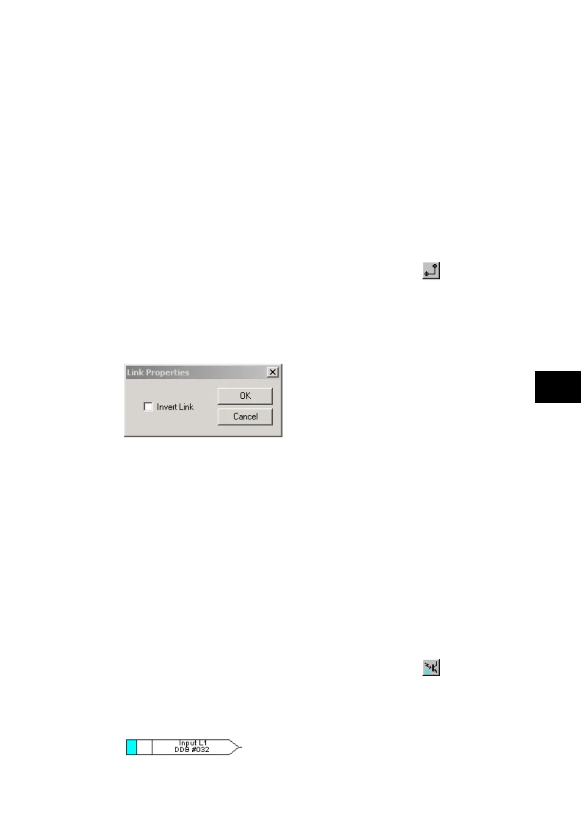
1.6.1 Link properties
Links form the logical link between the output of a signal, gate or condition and the input to
any element.
Any link that is connected to the input of a gate can be inverted via its properties window. An
inverted link is indicated with a “bubble” on the input to the gate. It is not possible to invert a
link that is not connected to the input of a gate.
Rules for Linking Symbols
Links can only be started from the output of a signal, gate, or conditioner, and can only be
ended on an input to any element.
Since signals can only be either an input or an output then the concept is somewhat
different. In order to follow the convention adopted for gates and conditioners, input signals
are connected from the left and output signals to the right. The Editor will automatically
enforce this convention.
A link attempt will be refused where one or more rules would otherwise be broken. A link will
be refused for the following reasons:
• An attempt to connect to a signal that is already driven. The cause of the refusal may
not be obvious, since the signal symbol may appear elsewhere in the diagram. Use
“Highlight a Path” to find the other signal.
• An attempt is made to repeat a link between two symbols. The cause of the refusal may
not be obvious, since the existing link may be represented elsewhere in the diagram.
1.6.2 Opto signal properties
Opto Signal
Each opto input can be selected and used for programming in PSL. Activation of the opto
input will drive an associated DDB signal.
For example activating opto input L1 will assert DDB 032 in the PSL.