P74x/EN MT/N
1, P742, P743
(MT) 11-
1.3.2.5 Replacement of the relay board in the power supply module
Remove and replace the relay board in the power supply module as described in above.
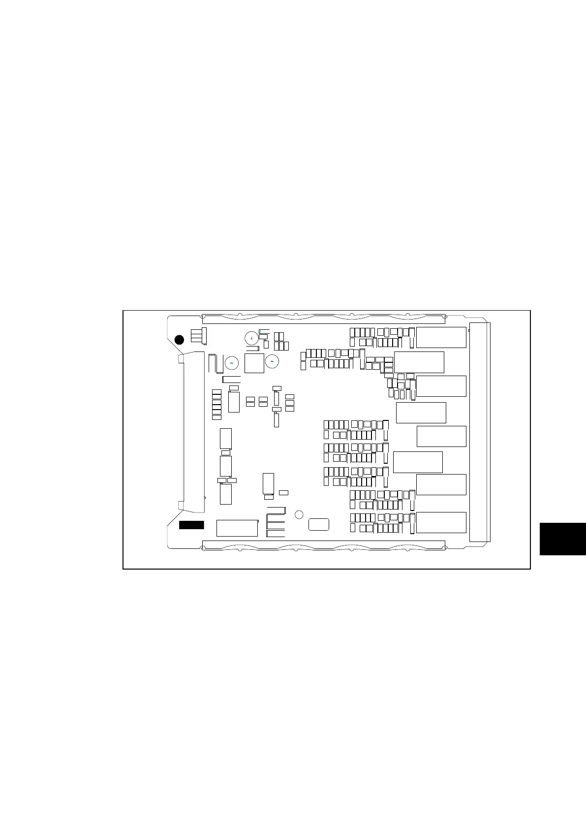
The relay board is the one with holes cut in it to allow the transformer and two large
electrolytic capacitors of the power supply board to protrude through. To help identify that the
correct board has been removed, Figure 11 illustrates the layout of the relay board.
Fit jumpers in slot positions as shown in Figure 2, 3 or 4.
Before re-assembling the module with a replacement relay board check that the number on
the round label adjacent to the front edge of the PCB matches the slot number into which it
will be fitted. If the slot number is missing or incorrect write the correct slot number on the
label.
Ensure the setting of the link (located above IDC connector) on the replacement relay board
is the same as the one being replaced before replacing the module in the relay case.
Once the relay has been reassembled after repair, it should be recommissioned in
accordance with the instructions in sections 1 to 8 inclusive of the commissioning and
maintenance section P74x/EN CM.
E2
SERIAL No.
ZN0019
F
P3762ENa
FIGURE 11: TYPICAL RELAY BOARD
1.3.2.6 Replacement of the opto input, high break and separate relay boards (P741, P742, & P743)
To remove either, gently pull the faulty PCB forward and out of the case.
If the relay board is being replaced, ensure the setting of the link (located above IDC
connector) on the replacement relay board is the same as the one being replaced. To help
identify that the correct board has been removed;
− Figure 12 illustrates the layout of the opto board,
− Figure 13 illustrates the layout of the high break relay board,
− Separate relay board is illustrated in the Figure 11.
Before fitting the replacement PCB check that the number on the round label adjacent to the
front edge of the PCB matches the slot number into which it will be fitted. If the slot number
is missing or incorrect write the correct slot number on the label.
Fit jumpers in slot positions as shown in Figure 2, 3 or 4.