P74x/EN OP/N
(OP) 5-
5. COMMUNICATIONS BETWEEN PU AND CU
The P74x scheme can be either centralised in one cubicle or distributed in cubicles housing
other protection depending on the availability of space. Either way the Peripheral Units still
need to communicate with the central unit and vice versa. Each central unit has up to 7
communication boards each accommodating inputs from 4 peripheral units. Thus each
central unit can accommodate up to 28 peripheral units.
Note: From software E1.0, model 50, The CU and all the Pus must have the
same model number (digits 12 & 13). When a PU with a not
compatible model number and software reference is connected to a
Central Unit, the CU will not recognise the PU and will show the
Locking Level 2 Error and alarm.
5.1 Communications link
The following communication media is used for the communication channel within the P74x
scheme. The data rate is 2.5 Mbits/sec.
5.2 Direct optical fibre link, 850nm multi-mode fibre
The units are connected directly using two 850nm multi-mode optical fibres for each
signalling channel. Multi-mode fibre type 62.5/125µm is suitable and standard BFOC/2.5
type fibre optic connectors are used. These are commonly known as “ST” connectors (“ST”
is a registered trademark of AT&T).
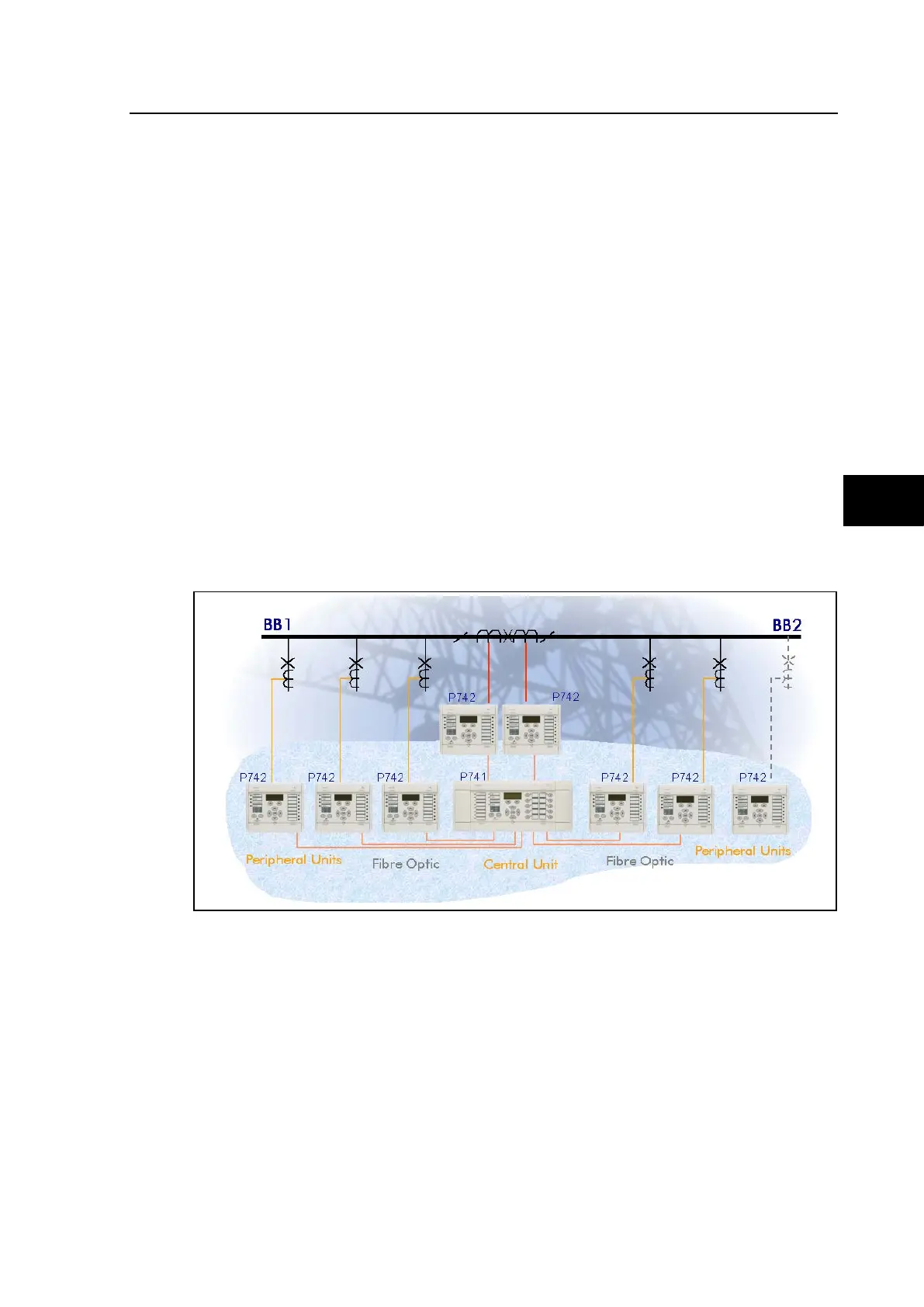
FIGURE 29: MODULE INTERCONNECTION
This is typically suitable for connection up to 1km.