P74x/EN MT/N
1, P742, P743
(MT) 11-
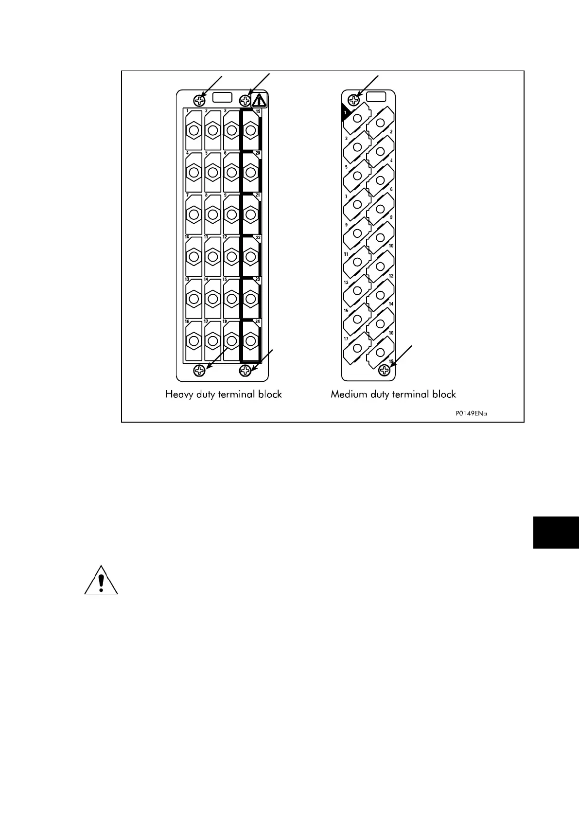
FIGURE 1: LOCATION OF SECURING SCREWS FOR TERMINAL BLOCK
Note: The use of a magnetic bladed screwdriver is recommended to
minimise the risk of the screws being left in the terminal block or lost
Without exerting excessive force or damaging the scheme wiring, pull the terminal blocks
away from their internal connectors.
Remove the screws used to fasten the relay to the panel, rack, etc. These are the screws
with the larger diameter heads that are accessible when the access covers are fitted and
open.
If the top and bottom access covers have been removed, do not remove the screws
with the smaller diameter heads which are accessible. These screws secure the front
panel to the relay.
Withdraw the relay carefully from the panel, rack, etc. because it will be heavy due to the
internal transformers.
To reinstall the repaired or replacement relay, follow the above instructions in reverse,
ensuring that each terminal block is relocated in the correct position and the case earth,
IRIG-B (Central Unit only) and fibre optic connections are replaced. To facilitate easy
identification of each terminal block, they are labelled alphabetically with ‘A’ on the left hand
side when viewed from the rear.
Once reinstallation is complete the relay should be recommissioned using the instructions in
sections 1 to 8 inclusive of the commissioning and maintenance section P74x/EN CM.
1.3.2 Replacing a PCB
If the relay fails to operate correctly refer to the Problem Analysis chapter, to help determine
which PCB has become faulty.