pplication Notes
P74x/EN AP/N
1, P742, P743 (AP) 6-
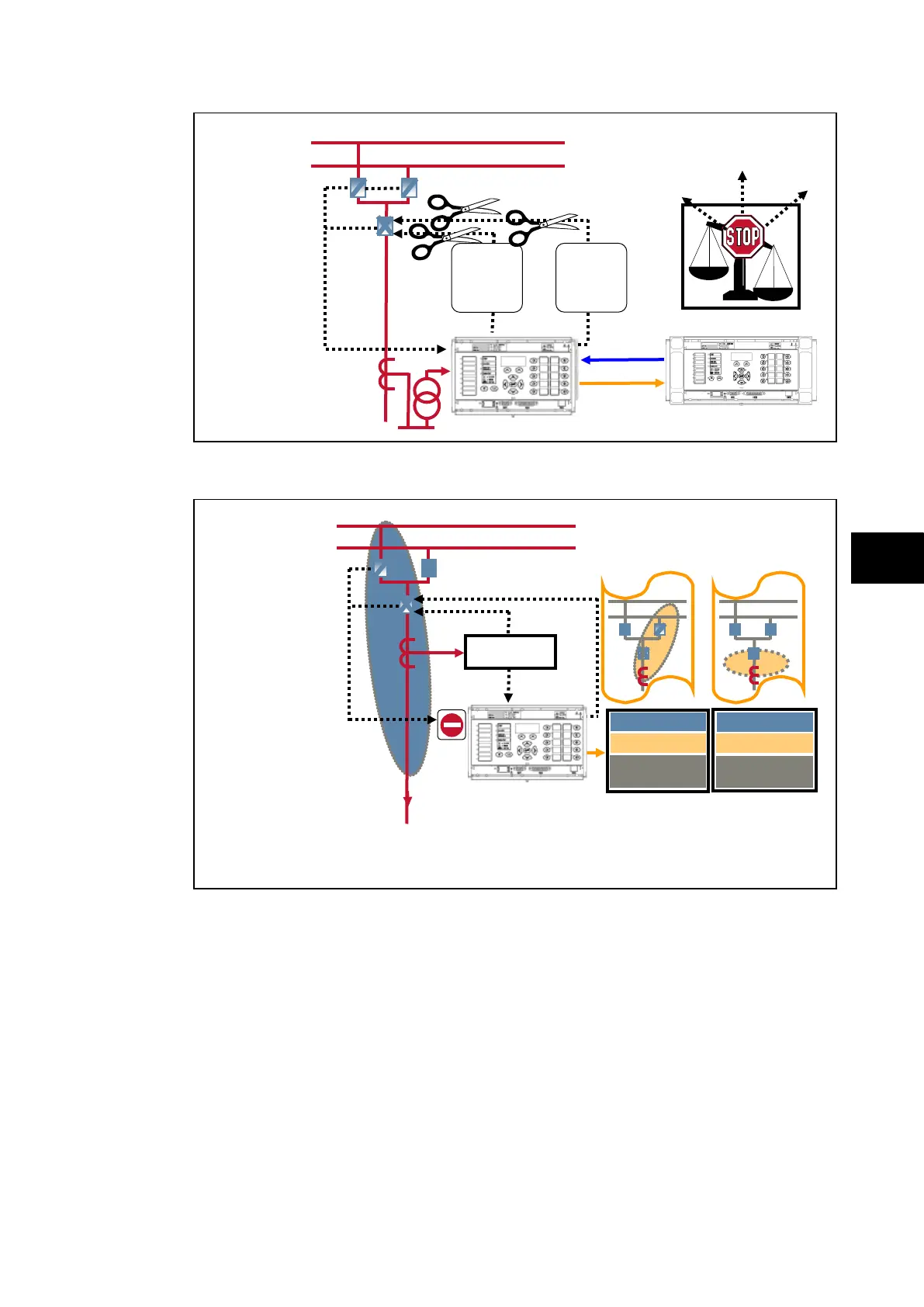
FIGURE 9 FORCING PLANT POSITION STATE
Under certain conditions it may be desirable to force the positions of the primary plant to
enable scheme testing to be carried out, for example during commissioning.
In the first example the forced scheme theoretically connects the feeder to busbar 2, whilst in
practice it is connected to busbar 1. Zone 1 will see a differential current equal to –i
load
whilst
zone 2 will see a differential current equal to +i
load
this will give a check zone equal to zero.
In the second example the forced scheme theoretically totally disconnects the feeder. An
end zone or extra node, is created by the topology in order to fully replicate the scheme.
This lies between the feeder CT and the circuit breaker.
However, it must be remembered that in practice the feeder is still connected to busbar 1.
Zone 1 will see a differential current equal to –i
load
. This extra node will see a differential
current equal to +i
load
and which when included in the check zone will give a result equal to
zero.
If done, to avoid any maloperation, the Central Unit must be in 87BB blocking mode while
performing these forcings.
trip order
to relevant
Service
At least one
isolator and
Response of the
Differential Elements
forced scheme =
Feeder connected
to BB2
1
BB
2
scheme = Feeder
disconnected
scheme:
Feeder
connected to
BB1
indication
to PU